Joe's E-bike build

How are you going to handle the water cooling? Will you be needing a pump?
Yes, I have a small 12 volt pump I'm planning to use and a heat exchanger for PC water cooling. There are pics of those earlier in the thread. I'm not sure how big the heat exchanger will need to be yet so I'm going to start out with the PC one and if it gets hot I'll move to an automotive transmission cooler or a motorcycle radiator. I plan on having a small tank somewhere on the bike to act as a coolant reservoir. The pump will run on an adjustable buck converter that can accept up to 96v input and outputs whatever you adjust it to so I can adjust the speed of the pump.

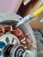
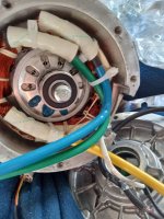
On another note I tried to solder one of the phase wires on the motor but my iron just isn't hot enough. I'll need to get a bigger iron to do it right. After removing the crimp connector o saw that although the enamel is removed from the wires and they were all in contact with either the crimp connector or the phase cable, there wad only a small dab of solder connecting the magnet wire to the crimp connector and almost none inside the connector. I will be removing the crimps from all 3 and soldering the wires. I'll probably buy some kind of copper tube splice connector to go over the wires and solder them inside it to keep things tidy since twisting two big thick stranded cables like this together usually leaves you with a big unruly joint. The crimps probably work but I prefer everything to be totally soldered. It's mainly for my peace of mind.
 
A good crimp with a proper crimper with the right die for the shape and size of contact or tube being used will be much better than solder--it essentially turns the whole crimped set of wires/etc into a single piece of metal. If it's crimped properly, solder will not be able to get into the crimp, there won't be any space for it to enter, so having no solder inside the crimp can be a good sign of it having been done properly.

Soldered wires can be more breakable, the solder tends to wick up into the insulated part and makes a section of the wire stiff. Then the rest of it that's still flexible bends in vibration, and over time the wire strands can break at the interface. Strain relief of various kinds, including fully securing the entire length of wire to something stiff, can help with that, but I'd go with a good crimp wherever it's possible over a soldered connection.

The solder is also higher resistance than a good crimp.

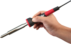
If you really want to solder something like phase wires, or heavy gauge battery wires, a "chisel tip" iron that's 80-100w should work. For wires that size (up to 8-10g so far), I use the older version of this Weller:

1700464602909.png

If you do want to solder them, I recommend this method:
 
That is good info, thank you! So, basically, I ripped the connections apart for no reason? :) Haha. I never knew that a crimp could actually be better than a solder joint. Ive had bad experiences with poorly done crimps on vehicles I've worked on in the past. I'm probably overly biased against them because of that. What you're saying makes a lot of sense though.

The crimps on this motor do seem to be done pretty well. Probably with some kind of machine. With mass produced stuff like this I'm always skeptical about certain things and I had to see for myself whether these connections were done correctly. My biggest fear was that some of the strands of magnet wire might not be in electrical contact with the phase wires and cause the ones that are to carry extra current. I'm not confident that I can make new crimps that will be better than what I could do with a solder joint unless i buy a special tool to do so. I could either buy that or buy a big iron and I feel like I could put the iron to more use. There is also the issue of solder already joining some of the magnet wires together so I'm not sure if crimping over top of those wires with solder I between would be a good idea. I suppose it might just squish the solder and still make a good connection but it could also just crack and create small voids. Maybe I'm overthinking that but, at this point, I'm still planning to solder them. I did try to solder one last night with the same method you showed in the pics in your other post where you kind of fan out the strands and intertwine them. That's the method I typically use for thick wires or when I want the joint to be compact. The plated phase wires QS used are twisted tightly together inside the insulation so they kind of puffed out when I did this creating what would be a large joint. I'm wondering if I should use barrel type splice connectors and fill them with solder or just tightly wrap a another piece of wire around the splice before soldering. There will be enough room for either method. I'm leaning towards using the barrel splice connector because I can get them locally and I've had good luck with those and soldering lugs onto thick wires the same way.

Anyway thanks again for that info. I did some reading on the subject now that you brought it up and what I've been reading seems to be in agreement with you. I don't think I'll have an issue with the solder wicking too far under the insulation since the strands are so tightly bundled but regardless I will be sure to secure the wires tightly again to help prevent vibration. I still have until this weekend to do more research and decide what to do next. I want to have the motor back together and sealed up by then so I can use it for mock up. I don't want the end covers off nearby where I'm grinding and drilling metal things.
 
I never knew that a crimp could actually be better than a solder joint. Ive had bad experiences with poorly done crimps on vehicles I've worked on in the past. I'm probably overly biased against them because of that.
I'd venture that there are more bad crimps than good ones. ;)

The only way to know if a crimp is good is to destroy it by cutting in half to see the crossection, though you can guess it's good if it will take the full current it's rated for with no heating, and/or has only the same resistance as the wire going into it (as measured with a meter like the DE-5000 that can do microohms or less, not a normal multimeter).


I'm not confident that I can make new crimps that will be better than what I could do with a solder joint unless i buy a special tool to do so.
Hydraulic crimpers aren't cheap but if you expect to do a lot of crimps are not all that expensive and would do a great job if you use the right size and shape of die for the contact or barrel used.

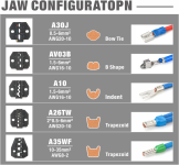
Even cheap simple ratcheting crimpers like this

1700514489337.png 1700514616991.png
work well enough; it's what I use for heavy-gauge stuff these days. There are better ones; it was the cheapest one I could find that still did the job I needed.


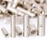
I got these
Amazon.com
1700514742096.png 1700514794698.png

There is also the issue of solder already joining some of the magnet wires together so I'm not sure if crimping over top of those wires with solder I between would be a good idea. I suppose it might just squish the solder and still make a good connection but it could also just crack and create small voids.
In a proper crimp, the solder will just compress like the wire and become part of the metal in the joint, even though it's fractured and broken up during the crimping process.


Maybe I'm overthinking that but, at this point, I'm still planning to solder them.

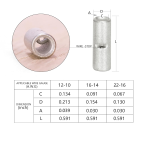
You can use those butt-splicers I linked above to do this, or the method I showed; either works well enough, though the crimp should be better / lower resistance. I wouldn't fill the splicers with solder first, just put the wires in, then solder with the big fat hot iron. The splicers have a wire-stop indent that is also a hole into the splicer that you can feed solder into. Let it reheat after doing one while you setup the next one (only takes a couple minutes or less).


Keep in mind that the solder in any barrel buttsplice like this is doing the current-carrying, so it's higher resistance does limit what the joint can carry to somewhat less than what it would if it were only the wire itself doing the direct connection (which is why I prefer to do the interlacing and tying down when doing soldered buttsplices, as it gives at least a little more direct connection of wire to wire).

If you do the wire interlacing first, and a barrel over them that then contains all the wires, then the resistance is lower, but still not quite as low as a direct crimp splice.


I did try to solder one last night with the same method you showed in the pics in your other post where you kind of fan out the strands and intertwine them. That's the method I typically use for thick wires or when I want the joint to be compact. The plated phase wires QS used are twisted tightly together inside the insulation so they kind of puffed out when I did this creating what would be a large joint.
That's where you have to tie them down with another strand of wire wrapped as tightly around them in a spiral as you can, secure the ends and then solder. This forces the wires as closely together as youc an get them.

Sometimes you just have so many strands that you may have to fold back the outer layers of the one with the smallest strands and cut off enough of the inner layers of strands to fit the thicker ones in between them, and then do the splice. The current has still been carried up to the splice, so is not much extra resistance to do this (but if you require a smaller joint for whatever reason, it makes that possible).


Anyway thanks again for that info. I did some reading on the subject now that you brought it up and what I've been reading seems to be in agreement with you. I don't think I'll have an issue with the solder wicking too far under the insulation since the strands are so tightly bundled
You'd be surprised how far it will wick up in those conditions--it's actually more conducive to wicking than strands that are far apart. If you have to hold the iron on the joint very long, it will heat the strands enough especially at the core to let the already-melted solder stay melted and continue wicking up.

That's one reason for using a big fat iron--it carries a lot of heat in that fat tip so it rapidly heats the joint for you to melt the solder into, so you don't have to hold the iron on there very long to do the job, and minimizes wicking and also insulation damage (or component or PCB damage when soldering fat wires to PCBs).
 
FWIW... I mostly crimp, but occasionally resort to solder, depending on location. If I suspect high moisture exposure, I tend to add solder to inhibit joint corrosion. Aircraftspruce has numerous crimpers (some near $600... if you can believe it) and a variety of terminals. Didn't find any 'solder' however.

Electrical | Aircraft Spruce
 
AW has already nailed it, however I'll add that when googling big soldering irons look up 'stain glass soldering irons' I think I paid $12 for mine. It doesn't get a lot of use but is useful every once in a while. Hydraulic crimpers are tits, but I can't justify the cost. I have the crimpers Amberwolf uses. For stuff that doesn't get a lot of vibrations or flexing, I Interweave, crimp and then solder.
 
Ok, so, I got a big soldering iron from the hardware store. I got the connections soldered up and I'm happy with the way they turned out. I sure did use a lot of solder on these! I'm going to have to buy some more. I used the intertwining method then I used vice grips to clamp the strands together as tightly as I could and tied a piece of solid copper wire around them to keep it all tight while I soldered. I put new heat shrink over top before zip tying the wires tightly back to the coils the way they were originally.
IMG_20231124_130900374_HDR.jpgdont worry I got all that crap off the rotor before I put the cover back on.
IMG_20231124_143543794_HDR.jpgI sealed the plastic grommet all the way around when I put it back in. There wasn't any silicone around the part that slides into the slot in the housing originally. I used permatex ultra black RTV silicone. I use this stuff on all the vehicles I work on and it's great. I use it for everything from thermostat housings to water pumps to oil pans. It's a great general purpose silicone sealant and it has good resistance to chemicals and oil. It dries a little stiffer than some other types but not extremely stiff like their ultra gray.

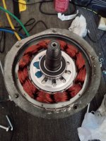
Here's where things get interesting. After sealing up the back cover I removed the front.
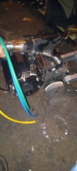
IMG_20231124_153202387_HDR.jpgI had expected to be able to see into the water jacket from here but nope! So that means the housing must have a hollow portion around the outside of the stator with another piece of aluminum covering the opening. I can't see this because the stator is totally covering the area. I can see inside the holes for the water fittings and I do not see the laminations of the stator. I don't know a whole lot about the casting process but it seems impossible to cast a hollow housing in this shape. So this must mean it has another piece inside that wraps around the stator and is somehow sealed at the ends. I put my mouth over the bolt holes for the cover trying to see if I could blow air into them and feel it come out the holes for the fittings but I could not. I'm surprised by the way this is constructed. It's not at all what I expected. It just leaves me to wonder how they sealed the water jacket. I'm not going to try and remove the stator from the housing. I think I will ruin it if I try that. So I guess all I can do is speculate. I stuck a zip tie into the holes for the fittings and it is indeed hollow inside so it's not a fake water jacket.
 
Late to the party, but wanted to add, depending on application, I have successfully just used a blowtorch when I need to solder something huge and coppery. Like when I need to literally fill a lug or cup connector with solder.

I wonder if it would work for this application? I would think not, because so much heat would probably travel further downstream into the windings than what you'd like.
 
A torch probably would have worked. I don't have one though and I needed a big soldering iron. I looked at some smaller butane torches when I went to get the iron today. My main concern was the possibility of getting soot in the joint. If I had used one of the barrel type splices I'm sure a torch would have done the job. Or if I hit it with a torch after soldering just to make sure the solder wicked all the way into the middle of the splice. I've used a torch on copper lugs before too. It definitely works. Especially if you're out in the driveway making battery cables without an extension cord nearby. Easier just to use a torch.
 
Keep us informed on the water cooling. Sounds interesting.
I would prefer ethanol cooling like the radar of a MiG 25. That way it can serve an actual purpose when desired, after the fetishistic novelty has worn away. 🥃
 
Keep us informed on the water cooling. Sounds interesting.
I definitely will! I'll be working out the details of the system soon. The location/size of the reservoir kind of depends on how I end up mounting the controller and the battery. After I have the motor and the crank/pedals on the frame I'll start to focus on those things. I just ordered the boards and the components for my Lebowski controller yesterday so I'll be working on getting it up and running in the coming weeks.
I would prefer ethanol cooling like the radar of a MiG 25. That way it can serve an actual purpose when desired, after the fetishistic novelty has worn away. 🥃
Haha. Well, I can't say that you're wrong. In all honesty this motor will rarely see any real abuse and with this setup it's probably not even going to sweat.At least I'm hoping not. If the motor is really so inefficient to need liquid cooling to stay alive then it's probably not designed very well. My thinking is that I can gear it high for good torque from a standstill but if I want to rev it out occasionally for a speed run the water cooling will allow me to push it outside it's efficiency range for a short time. Will it work out that way? I don't know. This is the first experience I've ever had with something like this.

Then, of course, there's the fetishistic novelty of a water cooled e bike. I may even use clear vinyl tubing and an acrylic reservoir with UV LEDs pointed at it.;) they see me glowin... they hatin...
 
Haha. I've seen some pretty slick water cooling setups on PCs actually. It can look pretty cool if it's not too overdone. I was mostly joking but it might be useful to have a way to see inside the reservoir. This thing is already going to look pretty crazy as is and I'm not trying to attract any more unwanted attention to myself. Vinyl tubing does not weather well outdoors either. My goal is reliability so I'll be using rubber hose of some kind. Probably some fuel injection line with good clamps. Something I can get at any auto parts store.

I had to Google noctua. Ive been out of the PC building loop for a long time. I had a similar cooler to that at one point. To replace my giant circular zalman one with the 120mm fan that laid flat and covered one of the RAM slots... back in the good old socket 939 days with the opteron 165.
 
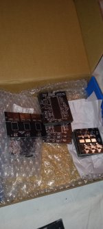
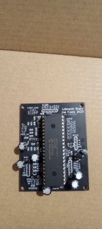
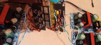
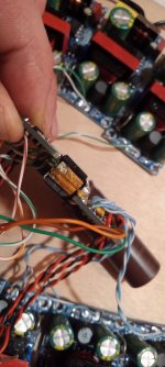
My boards came in today. Apparently DHL delivers on Sunday that was a nice surprise. The brain board is complete. Waiting for my pickit 3 to show up so I can program the chip now. I'm waiting on the copper sheet for my bus bar and some various resistors before I begin constructing the MOSFET board.IMG_20231203_181259267.jpgi got 10 of each board. One is the output section with the mosfets and gate drivers, one is the Lebowski brain without the power supply section and one is just for the current sensors.
IMG_20231203_181322608.jpg
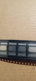
These are the mosfets I plan to use. They are pricey but I like the fact that they have so many extra pins and the top side cooling package. 8 of the pins are for the drain 7 are for the source and 1 is the gate. Their max continuous drain current is rated at 331 amps.IMG_20231203_181346370.jpgi used the 40 pin dip version to allow the chip to be swapped out easily. I have some Chinese buck converters I will be testing for power supplies and when I get something's working I plan to make a separate power supply board to feed this and the gate drivers. My high side gate drivers need an isolated supply since I am not utilizing a bootstrap circuit. This is my first SMD project and I have to say that it really isn't so bad after all. I had always feared SMD stuff and avoided it. This is also the first time Ive ever had boards made. I've etched my own in the past. It was fun and kicad isn't too hard to learn. There's a lot less room for error when you draw the schematic and then layout the board from it. Staring at it for possibly hours on end. Hopefully I didn't make any silly mistakes! I used lead free solder on the brain board and I didn't like it. Its not horrible but I like the lead stuff better.
 
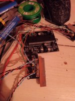
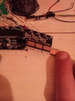
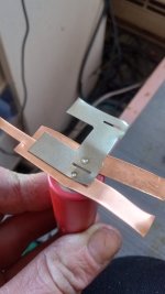
I got the brain board up and running this week. I was sick last weekend and didn't go work on the bike I just stayed home and worked on the controller project. I have the output section mostly together. My original plan didn't work out exactly how I imagined it would because the pins on the mosfets are too short to extend to the opposite side of the board but I came up with an alternative that I like. I think its actually better this way.IMG_20231213_173240_01.jpgI cut the center part of the board out so that the high and low sides are separate boards with the bus bars in between. I then cut small L shaped pieces of copper to connect the source and drains together where the output of the half bridge is. The above picture shows the high side board with 2 of the 3 L shaped pieces of copper soldered in. The mosfets are on the underside of the long strip of copper which serves as the positive side of the bus bar.IMG_20231213_173310_01.jpgthis is the low side before I soldered it all together(it says hi on the silkscreen but I labeled it wrong). The 8 pins sticking out not connected to anything are the drain pins.

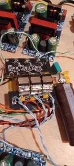
IMG_20231214_200208384.jpgthis is what it looks like now all together. There's a piece of kapton tape in between the bus bars. The blue and white wires are the isolated gate drive supplies for the high side. I actually have this set up with 6 individual isolated 12volt supplies. One for each gate driver chip. The phase wires will be soldered to the L shaped copper pieces somehow. I haven't quite figured out how to move forward with that step yet.IMG_20231214_200231776.jpgheres another view showing it from the other sideIMG_20231214_200316378.jpgand a view from the end where you can see both sides of the bus bar and the L shaper copper piece connecting two of the mosfets together through the rectangular cutout in the board

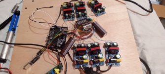
This whole thing when completed will be sandwiched between two aluminum water blocks. I have two 40mm*40mm gpu water blocks that I plan on using. The heat exchanger is also aluminum which is why I'm not using copper water blocks. Although I probably wouldn't have any galvanic corrosion issues anyway due to the fact that the coolant shouldn't get contaminated but I want to play it on the safe side. The motor is also aluminum and it would suck if the water jacket started to corrode. I still need to get some thermal pads or mica sheets to insulate the mosfets. The drain is electrically connected to the metal pad on the front face of the mosfet. I think I'm going to use a thermal pad because of the extra cushion they have. That should help with vibration and I can also get a little more clearance for the wires with the extra thickness a pad can have.IMG_20231214_200158471.jpgthis is the whole test setup. I don't have a throttle yet either so at this point I've only tested it with the PWM test mode and with no load on it. It does operate correctly but we shall see what happens when I connect a load to it. The gate driver chips have separate positive and negative outputs for the gate so that you can have separate gate resistors for turn on and turn off without using a diode. I'm using a 22 ohm for turn on and 10 for turn off. I know that's a little high but I can always change them later is it's too slow. Like I said I haven't connected a load to it yet but with no load there is no significant ringing at 20khz. There is a very slight overshoot on the turn on but I think it's within normal. My scope is really not good either but its been serving it's purpose so far.

I'm having a weird issue with my brain board. I used the schematic Lebowski made when I designed my version and I included the two transistors to invert the TTL serial lines and buffer them so that a standard serial port can be used but I ended up removing those components because my USB to serial converter is non-inverted TTL(ch340). For some reason I can't get the chip to reset when the Tx from the USB to serial converter is connected. I have to disconnect the Tx line reset the chip(at which point I get the configuration menu in my terminal window) then connect it afterwards. After that the rs232 works fine in both directions. I'm confused as to why this is happening and it's kind of annoying.
 
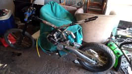
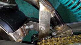
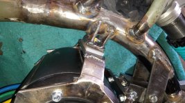
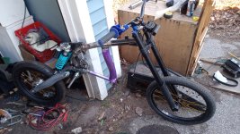
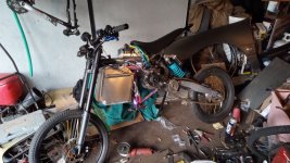
Made some progress this weekend. I have the jackshaft and the motor mounted to the frame now. I still need to reinforce it a little but it's most of the way done. The bracket for the motor bolts on and allows some degree of adjustability. I'll be adding a few more attachment points when I decide exactly how I want to do that. It's not perfect but I'm happy with it so far.
IMG_20231223_183809806.jpgIMG_20231223_105003481.jpgVID_20231223_161827324_exported_6417.jpgVID_20231223_161615557_exported_32426.jpg
 
Added the seat mount. I was able to sit on the bike for the first time!
IMG_20231231_174118165.jpg
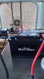
I'm going to begin construction of a smaller test battery pack soon. I want to build a smaller one to get some experience with it before I go all out. I am unable to fully test my controller because I don't have a big enough power supply. The biggest thing I have is a 19v 5A laptop charger which isn't even enough to do the FOC calibration. It trips the short circuit protection almost immediately and all I get is a little hum and an error. I tried to use an 8ohm 100watt resistor in series and it completes the test this way but says "overflow error". I fixed my weird rs232 issue with the controller as well. It turns out I was not operating it correctly. The code requires a character to be sent to the controller from the terminal before it will display the configuration menu. This is clearly stated in Lebowski's manual but I somehow missed it.
 
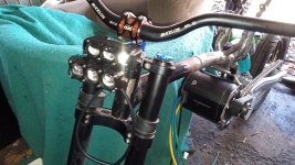
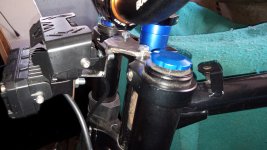
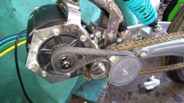
I got some more work done on the bike this weekend. It's been pretty cold lately but we finally got a little break in the weather. I got the motor mounting, belt, chain, and rear sprocket sorted. Also made a headlight mount.

IMG_20240213_141603940.jpg
IMG_20240213_141547064.jpg

IMG_20240213_141526753.jpg

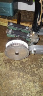
I used a timing belt tensioner pulley from my old 87' Plymouth Voyager with the 3.0l V6. The timing belt on that engine is the same width as this belt and I had an old one in storage. It's a readily available part and has a nice big bearing in it. The slot in the middle for adjustment makes things easier.
IMG_20240213_141617944.jpg

I finally settled on a design for the motor mount. I spent a lot of time thinking about how to go about it because I wanted it to have adjustability but also be very rigid. The "C" shaped piece in the middle is slotted so it can slide in and out where it's bolted to the inside of the 45 degree braces.
IMG_20240213_141633464.jpg
There is a hard piece of silicone between the motors bracket and the upper mount on the frame so I can use the adjustable lower mount to get the pulleys aligned and then tighten the upper mount down on the rubber. The rubber compensates for the fact that the upper mount isn't perfectly square. I may end up replacing the rubber with a steel shim ground to the correct angle but the rubber actually works well for this so then again I may just leave it like that.
IMG_20240213_141640931.jpg
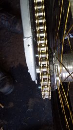
For the rear sprocket I ended up using a 530 sprocket for a Honda application. I had to use a die grinder to grind out the center bore to 94mm to match the moped hub and then drill new mounting holes. This was a very tedious process. The metal that the sprocket is made from is very very hard metal and was a huge pain to grind and drill through. I made an adapter plate from the moped sprocket by cutting off everything but the center ring where it bolts to the hub and then drilling three holes to match the Honda sprockets new bolt pattern. I counter sink the holes and used flush Allen bolts for the mounting bolts that connect the "adapter" to the hub and put spacers between it and the Honda sprocket. I made two plastic spacers from a cheap cutting board I bought at Walmart. Those are the black pieces you see in the photo below.
IMG_20240213_141702545.jpg
I'm still saving money for cells. I've settled on molicel p42a cells. I was originally thinking I would use 18750 cells but after all my reading on here and elsewhere it just makes more sense to use a 21700. I can get a much higher capacity and the extra physical size is negligible in my application. Molicel has reportedly announced the release of a new p50b cell coming soon but I don't think I can wait that long. I'll probably be kicking myself later on when the price of the p42a and p45b goes down because of this. Next time I guess.

I've been slowly making progress on the controller as well. Right now I'm working on a power supply board to replace the 7 individual power supplies I used for testing. I need 5V for the brain board, the current sensors, the logic side of the gate drivers, and the Bluetooth module(more on that in a moment). At least 3 isolated 10V supplies for the high side gate drive and one extra 10V supply for the low side. It's a challenge because I don't want it to end up being a gigantic board. There are several ways to go about the regulation scheme. I contemplating on whether I want to step the battery voltage down to a intermediate voltage like 24v with a big regulated buck converter and then use unregulated(open loop) flyback converters for the individual supplies or just make one big transformer with multiple secondaries for everything and regular it with a feedback winding.

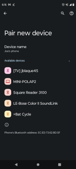
Oh yeah about the Bluetooth thing. I have Bluetooth working on my Lebowski board now. It's very simple to do this using an HC-05 Bluetooth module. There are terminal emulator apps for Android that will connect to the HC-05 and allow you to program the Lebowski board with your phone.
Screenshot_20240129-181412.png
Screenshot_20240129-181611.png
 

Attachments

  • Screenshot_20240129-181412.png
    Screenshot_20240129-181412.png
    205.1 KB · Views: 3
  • Screenshot_20240129-181412.png
    Screenshot_20240129-181412.png
    205.1 KB · Views: 4
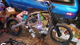
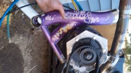
Got to work on the bike this weekend. I finally found a suitable donor bike for the bottom bracket shell and associated tubing. Turns out I was looking in all the wrong places. Behold!
VID_20240303_125933508_exported_6494.jpg
The purple princess bike!
VID_20240303_125933508_exported_16078.jpg
IMG_20240303_155745861.jpg
IMG_20240303_175443417.jpg
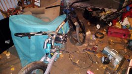
It was the perfect shape and put the pedals right about where I want them. It's also made of some cheap carbon steel which welded very nicely to the rest of the frame. I won't be using the tiny crank I just put it on there to see how the pedal position felt sitting on the bike. I also added a second rear shock. One wasn't stiff enough but I had originally ordered a set of two so rather than buying another stiffer one I just added the second one. The seat bracket was too narrow to accommodate the second shock so I cut it off again to move ot forward slightly. I haven't re welded it yet because I'm rethinking the design.

I didn't get a good picture of it, but I got a freewheel adapter that fits onto the 3/4" jackshaft. No freewheel yet. I'm planning to use a 12 tooth freewheel on the jackshaft with something like a 52 tooth chainring on the crank. Despite what some may think when they see what I'm building here, I do fully intend to pedal this. At least to some degree. I ride a bicycle everyday and this is to allow me to travel longer distances and with more cargo. Ive been looking into adding pedal assist to the setup as well. I think the cycle analyst will work for that.

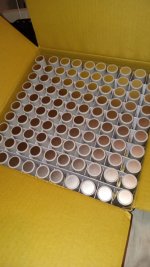
I also received two boxes like this
IMG_20240303_190653685.jpg
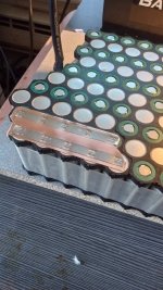
Molicel p42a. I'm going to be starting the construction of the battery in the coming weeks. My original plan was to do 20s8p but the price goes down at 200 cells so I decided to order 200 for 20s10p. 205 actually so I have a few extras just in case. This means I need more cell holders too so I'm waiting on some packages from china now. I'm planning to do the copper nickel sandwich technique. I'll use long strips of .2mm copper sheet with small squares of nickel plated steel to facilitate welding. I'm in the process of building a spot welder with a rewound MOT and an aliexpress spot welder board. I've modified the board to work from a separate 12v supply. This means the welding voltage can be lower and the mosfets on the spot welder board will still turn on. We'll see how well that works out. I need a large bridge rectifier module to complete it and do real testing as I've exploded all of the small diodes I had on hand just messing around with it. I'm not sure the MOT will be enough amperage but If all else fails, I'll use a lead acid battery instead of the MOT. I just wanted the convenience of a welder I can plug into the wall.
 

Attachments

  • IMG_20240303_175443417.jpg
    IMG_20240303_175443417.jpg
    4 MB · Views: 13
I finally found a suitable donor bike for the bottom bracket shell and associated tubing. Turns out I was looking in all the wrong places. Behold!

The purple princess bike!
Make sure you test it well. The BB section can be one of the most stressed areas. Especially when standing on one pedal.
 
Make sure you test it well. The BB section can be one of the most stressed areas. Especially when standing on one pedal.
Thanks for the tip. I'll definitely keep an eye on it. Maybe I should ride it around with no motor once I get a more suitable crank and the freewheel on. I did stand and jump on the pedals after I welded it. And rode it around in the driveway scooter style on one pedal. Although It seems very rigid as is, I feel the lower part needs more support where it's welded to the flat stock(maybe difficult to see that in the pic). I ran out of time though. I spent a lot of time notching it perfectly to the main tube. I definitely understand your concern because it doesn't have a whole lot of lateral support aside from the welds themselves. There are also no chainstays(is that what they're called?) anymore to provide that kind of support against twisting motion. The actual bottom bracket is pretty typical of what you would see on any cheaper(or older) bike with a single piece crank. The thickness seems good. I don't think it's made thinner simply because it's a child's bike. The bike was actually rather heavy for how small it was. The sparks from the steel were more indicative of a carbon steel however it didn't feel like hard steel when I was grinding it the way that actual 4130 does. It welded rather well too. The joints were all welded from the factory which is what caught my attention in the first place. I think it will work out. I like the curve it has in the tubing it just seems to fit well in my opinion.

Just for the record it will not stay purple haha. It will eventually be painted with the rest of the bike.
 
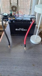
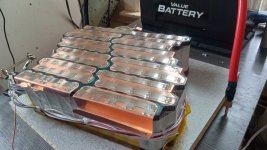
I got half the battery built. My MOT spot welder was not powerful enough for the copper nickel sandwich and I ended up blowing the mosfets during my experimentation. This was my fault because I accidentally let a wire touch something it shouldn't have. Since I wanted to get the battery done this weekend I rigged this up
IMG_20240419_173842220_HDR.jpg
I have a capacitor(2 in parallel actually) connected in series with the coil of an automotive relay with the relay switching 12v from a small switching power supply to a Ford starter solenoid. The capacitor serves as a timer for the weld pulse. There's also an LED connected in parallel to the capacitor to discharge it after the pulse and thus reset the timer. I have a sewing machine pedal to trigger it. I experimented with different capacitors and settled with two 470uf caps which gives me about a 120ms pulse according to my scope.
IMG_20240419_173849327_HDR.jpg
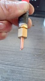
The electrodes that came with the cheap spot welder board that I was originally using were melting so I went to the hardware store and I found "belt rivets" which are copper rivets. I filed and sanded them to this shape. I bought NPT compression fittings from the plumbing section and soldered those to the ends of my cables. This allows the rivets to be replaced if needed.
IMG_20240419_173857676_HDR.jpg
IMG_20240419_174416288_HDR.jpg
Tested it on some junk cells and got good results.
IMG_20240419_185248445_HDR.jpg
This is .2mm copper and .15mm nickel plated steel.
IMG_20240420_152545381_HDR.jpg
IMG_20240420_162435037_HDR.jpg
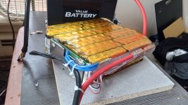
The finished pack will be two of these each with their own BMS. This BMS is not capable of handling the full current of the pack and it will eventually be switched out for a bigger one. I don't plan to set the the current to the max on the controller at first because I don't know how this bike is going to handle or how it's going to hold up structurally so these BMSs will do for now. They could be modded to handle more current because the board appears to be the limitation. The buss bars could be directly soldered to the MOSFET pins however there is conformal coating on the boards so I didn't do that yet. I also ordered a Fardriver 72360 to use until I finish the Lebowski controller. It's getting warmer and I want to get it running so I broke down and bought the Fardriver. On that note, I have also made progress with the Lebowski controller and it's ready for a housing. I should be able to test its capabilities with 6 mosfets here very soon. After that I'll add additional parallel output stages.
 
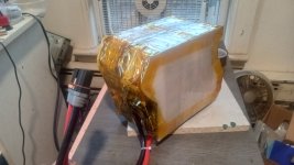
Got the rest of the battery done this week. The two packs are separated by two layers of heat resistant foam padding with a sheet of fiberglass sandwiched between them. The ends of the packs which will be in contact with the steel housing are covered by 5mm thick silicone sheeting. I have some phenolic panelling that's about 3mm thick. I plan to put more of the heat press foam around the outside of the pack with the phenolic board over top to give it more structure and then shrink wrap it. I have to get to the garage to cut the phenolic to the right size.IMG_20240426_172656851_HDR.jpg
I'm going to the garage to work on the bike tomorrow. I have the fardriver and I just need to build a housing for this pack. I'm thinking I'll build some kind of rails into the frame so I can slide the pack in and out from the side. Then I just have the brakes and the crank to work out and I'll have the main mechanics all finished. After that it's just the cooling system and the wiring. I'll make some guards for the belt and covers for the electrical components to keep them dry. Then tear it all back apart to sand and paint.
 
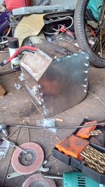
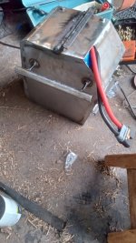
I finished the battery box earlier. Almost. It still needs to be sealed up and I have to modify the cover a little bit so it fits right but it's on the bike now. I made a track so that it sort of slides in from the side and then I latch it in with the two toggle latches. The wire exit isn't going to stay like that. I'm going to make a plastic grommet and silicone it. The cover will get a big thick gasket and some silicone. I plan on coating the whole thing with flex seal or bed liner. Although I designed the box to be serviceable I don't plan on taking it apart often. IMG_20240504_180148892_HDR.jpg
IMG_20240504_180204683_HDR.jpg
IMG_20240504_180317176.jpg
I took it for it's first test ride today. It's fast. The brakes aren't working yet though so it wasn't a real test. Just up and down the street to see if the belt would stay on etc... it has a lot of torque that's for sure. Tomorrow I'm receiving the spacer and the brake line I need to get the magura mt5 hooked up to the brake lever. The rear brake needs some fabrication done which I've been putting off because it means I need to remove the back wheel which is a PITA to do in the cluttered area I have to work with. If all goes as planned, tomorrow evening I will ride it a longer distance and work the bugs out. Then it's on to the cooling system. I'll get some better pics of the mounting system for the battery too. I am absolutely stoked to have it moving under its own power.
 
Back
Top