KT tubullar contoller + LCD4 - empty battery bar, yet full voltage.

troyoo

100 µW
Joined
Jun 28, 2023
Messages
7
Location
Europe
Hi folks!

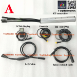
I've bought a KT 36V tubullar controller (julet plugs) kit with LCD4 display and PAS sensor. Paired it with AKM 250W 100 CST hub motor and Wuxing 108-2 thumb throttle.
1687986074813.png1687986240509.png

Thing is, when I had connected it for the 1st time, it run for few seconds, and then stopped reacting to throttle input. LCD4 display started showing empty battery bar, yet full battery pack voltage. Motor stopped running ofc. PAS doesn't work as well. I can go through every setting of the display and so on, reset it or whatever. It changes nothing, still won't work.

Seller sent me new 1-2 cable and new LCD4 display. Same story, plugged everything, it run for 3 or 4 seconds, motor shut down > battery bar went from full to zero. It doesn't run anymore. I've tested at least 3 different battery packs, same story - it shows correct voltage, yet it states they have no charge.

I've tried different controller with those parts, and still have the same problem. It's like the display gets fried or something after using throttle... WTH?

Any ideas?
 
Perhaps the controller or display is actually built or hard-coded for a different voltage battery pack, so that your battery(ies) are too low a voltage for what this system is looking for.

If the controller things the battery is empty (for whatever reason) it will not allow the motor to run.

It wouldn't be the first time this has happened with various controllers and displays over the years. The seller might not know anything about the problem, as it might be a firmware issue from the manufacturer.
When I connected both displays for the 1st time it has shown the battery with full capacity. Only when I pressed the throttle, enerything went wrong. LCD4 no longer sees any battery as full. Maybe the controller fries it once it gets to send full power to the motor? I've ordered a different controller and display setup to check another combo.

Seller replied to me that my battery is not good in that case, but I've tried running it with 3 completely different packs, that do run 100% on other bikes, yet not with this setup...
 
Try setting L1 = 2.

L Parameter Setting
1. L1 parameters are applicable to the automatic under-voltage controller. The
default of the factory is 0.
1.1 When L1=0, the automatic under-voltage controller can automatically select
the under-voltage value according to the battery voltage.
1.2 When L1=1, the under-voltage value of the automatic under-voltage controller
is forced to be 20V.
1.3 When L1 = 2, the under-voltage value of the automatic under-voltage
controller is forced to be 30V.

1.4 When L1 = 3, the under-voltage value of the automatic under-voltage
controller is forced to be 40V.
 
If you measure the voltage on the pins for the throttle or PAS connector on the controller side, are you still seeing 5V?
I've just ordered a multimeter to check the voltages, although all connectors are Julet waterproof, so it might be a challange, but will try that!

Try setting L1 = 2.

L Parameter Setting
1. L1 parameters are applicable to the automatic under-voltage controller. The
default of the factory is 0.
1.1 When L1=0, the automatic under-voltage controller can automatically select
the under-voltage value according to the battery voltage.
1.2 When L1=1, the under-voltage value of the automatic under-voltage controller
is forced to be 20V.
1.3 When L1 = 2, the under-voltage value of the automatic under-voltage
controller is forced to be 30V.

1.4 When L1 = 3, the under-voltage value of the automatic under-voltage
controller is forced to be 40V.

I don't think LCD4 has L settings, although C12 parameter seems simmilar to what You are refering to? Is that correct?
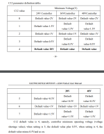
"C12 Controller Minimum Voltage Adjustment Setting"
1688061241451.png

Should I go with C12 setting "4" then?
 
although C12 parameter seems simmilar to what You are refering to? Is that correct?

I would not say that. C12 offsets voltage thresholds. But the thresholds are are decided by L1, which I think tells the controller the nominal voltage of your battery. L1 = 2 being a 10 cell 36V nominal voltage battery.
 
Last edited:
When I connected both displays for the 1st time it has shown the battery with full capacity. Only when I pressed the throttle, enerything went wrong. LCD4 no longer sees any battery as full. Maybe the controller fries it once it gets to send full power to the motor? I've ordered a different controller and display setup to check another combo.

Assuming correct wiring between them (which it has to have if it powers on normally and communicates), there isn't anything the controller can do electrically to damage the display in that event, in a way that would just change the battery level reading (which then triggers the system's protection against overdischarge).

Now, if the display were actually being damaged so it didn't turn on, or so that it could no longer turn on the controller, I could see how a flyback spike from a sudden current change in the motor thru the controller (if it's main bus caps are very insufficient or defective) could damage the display's transistor that turns on the controller's KSI line (so not providing power the LVPS to run the controller brain, preventing the controller from turning on), or the display's own LVPS (if the display didn't turn on at all).

Assuming the display directly reads the battery voltage and doesn't have the controller do it and send the data to it, then if something like this also damaged whatever reference the display uses internally for the battery readout, it might no longer be able to tell what the battery voltage is.

If the display gets the battery voltage as a data readout from the controller, then if the display's transistor that turns on the controller fails, the controller doesn't turn on so no data can be sent to the display, so no battery readout or anything else either, but the display itself would still turn on.


But if it isn't a hardware fault with the display, and it is something that happens *only* during controller/display interaction in taht specific scenario, the only thing I can imagine that could cause it is that incompatible data could be sent from one to the other that gets processed by some weird code in the display to write to the wrong location that changes what it sees as the battery cutoff, that isn't exposed as a user-alterable setting.
 
I've checked the voltage comming out of the throttle. It shows 0.8-0.9V no matter the lever position. Checked with 2 different throttles. FWIK it should read closer to 4-5V at full throttle, am I right? Or as controller sees the battery as empty, it doesn't allow to voltage to go higher in the throttle?

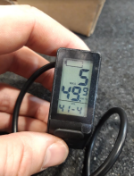
Also, during the 1st and 2nd attempts to run that system, before the battery capacity failure, the display has shown THX icon (that i'm sure of, not sure about PAS icon). Now it is missing, as well as PAS icon, like it's not seeing it as well? It reads 41.4V on the battery, yet no capacity.
1688216767876.png

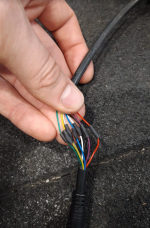
Also, I've managed to get into the 1T2 cable that connects the display and the throttle to the controller. Can I read anything usefull out of voltages there? Which wires should I check? Any ideas? (Green-Yellow-Grey-Blue-White-Black-Purple-Red)
1688216917611.png

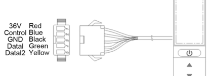
Wiring diagram for the display is down below:
1688216967620.png
Throttle runs on Gray - Purple - Black

Not sure what White cable is doing.

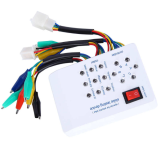
I've purchased the E-bike tester as well. Still got to figure out how to plug it onto my Julet plugs, but will figure something out.
1688217467638.png
 
I've checked the voltage comming out of the throttle. It shows 0.8-0.9V no matter the lever position. Checked with 2 different throttles. FWIK it should read closer to 4-5V at full throttle, am I right? Or as controller sees the battery as empty, it doesn't allow to voltage to go higher in the throttle?

The throttle control itself should vary the voltage out on it's signal line as it is moved.

The normal range is around 0.8v to around 3-4v, depending on the actual throttle mehcanical design inside (magnet type, placment, movement range, etc) and specific hall sensor used.

If it never does this, the most likely thing is that it has no voltage input to it. It requires 5v and ground into it to get any signal out of it (measured from signal wire to ground).

If it has no 5v to it, then the most likely problem in this specific situation is that the display is not turning the controller on by providing battery voltage to the controller's LVPS.

The next most likely thing is that the magnets have come loose inside it and are not being moved with the control, so it can't vary the sensor output. The sensor itself could have failed instead, but this is rare, and often results in zero volts output at all times, not just minimum voltage output.


Also, during the 1st and 2nd attempts to run that system, before the battery capacity failure, the display has shown THX icon (that i'm sure of, not sure about PAS icon). Now it is missing, as well as PAS icon, like it's not seeing it as well? It reads 41.4V on the battery, yet no capacity.
View attachment 335944

That image appears show it is reading a speed from the motor of 49.9km/h. Is that the case?

Usually this means that either the motor is spinning the wheel, generating a speed signal (couldn't be the case here), or it is getting a speed signal from something else (electrical noise?), or possibly that it is displaying random data because it doesn't know what else to do (bad software design).

If it is reading this speed, and it has a speed limit (built in or set by someone) below that speed, it will disable the motor to try to prevent going any faster.


Also, I've managed to get into the 1T2 cable that connects the display and the throttle to the controller. Can I read anything usefull out of voltages there? Which wires should I check? Any ideas? (Green-Yellow-Grey-Blue-White-Black-Purple-Red)
View attachment 335945

Wiring diagram for the display is down below:
View attachment 335946
Throttle runs on Gray - Purple - Black

Not sure what White cable is doing.

White is often used for a speed or temperature signal (or both, multiplexed) in motor cables. Don't know what it is in this one.

Given the signal naming provided, Control is probably KSI (keyswitch / ignition). If so, you should read battery voltage both there and on 36V lines with your red meter lead, with black meter lead on GND.

Data lines will read around 2.5v with a voltmeter, because they have constantly changing 0-5v squarewave signals on them that is serial data going to and from controller/display. If either reads just 0v or just 5v, it means no data is being sent on that wire.
 
The throttle control itself should vary the voltage out on it's signal line as it is moved.

The normal range is around 0.8v to around 3-4v, depending on the actual throttle mehcanical design inside (magnet type, placment, movement range, etc) and specific hall sensor used.

If it never does this, the most likely thing is that it has no voltage input to it. It requires 5v and ground into it to get any signal out of it (measured from signal wire to ground).

If it has no 5v to it, then the most likely problem in this specific situation is that the display is not turning the controller on by providing battery voltage to the controller's LVPS.

The next most likely thing is that the magnets have come loose inside it and are not being moved with the control, so it can't vary the sensor output. The sensor itself could have failed instead, but this is rare, and often results in zero volts output at all times, not just minimum voltage output.


That image appears show it is reading a speed from the motor of 49.9km/h. Is that the case?

Usually this means that either the motor is spinning the wheel, generating a speed signal (couldn't be the case here), or it is getting a speed signal from something else (electrical noise?), or possibly that it is displaying random data because it doesn't know what else to do (bad software design).

If it is reading this speed, and it has a speed limit (built in or set by someone) below that speed, it will disable the motor to try to prevent going any faster.


White is often used for a speed or temperature signal (or both, multiplexed) in motor cables. Don't know what it is in this one.

Given the signal naming provided, Control is probably KSI (keyswitch / ignition). If so, you should read battery voltage both there and on 36V lines with your red meter lead, with black meter lead on GND.

Data lines will read around 2.5v with a voltmeter, because they have constantly changing 0-5v squarewave signals on them that is serial data going to and from controller/display. If either reads just 0v or just 5v, it means no data is being sent on that wire.
So I've chopped an USB cable and used a phone charger to power up the throttle alone. It works just fine, 0.87V-4.45V at full throttle.

The 49.9km/h was max recorded speed by the controller, not a live readout.

Checked some other stuff with a multimeter today as well.

There were no shorts on the controller mosfets or whatever. No shorts between ground/motor phases/motor hall sensors, you name it.

What's more interesting, I've plugged a power supply to the controller and was still reading an empty battery. Something is wrong with that controller, not sure what exactly (yet).

I've tested other KT 36V controller and it works just fine, the same LCD as before, reads the battery capacity and voltage correctly. Definetly something is wrong with the controller then.

I'm in contact with the seller. If I get to keep the old controller I will take it apart and try to diagnose it for future reference.

Many thanks for all the suggestions and replies!
 
What's more interesting, I've plugged a power supply to the controller and was still reading an empty battery. Something is wrong with that controller, not sure what exactly (yet).

I've tested other KT 36V controller and it works just fine, the same LCD as before, reads the battery capacity and voltage correctly. Definetly something is wrong with the controller then.
Are you getting 5v out of the controller at the throttle's connector, it's PAS connector, and it's motor hall connector? If not, the controller is not being turned on by the display (no battery voltage on KSI wire) or the controller's LVPS is damaged.

Are you testing the controller without a display and seeing if it operates correctly? (requires connecting the B+ wire to the KSI wire at the controller's display connector to turn the controller on) If so, the display's KSI output is not providing battery voltage to the controller's LVPS to turn it on.

Are you testing the same display that does not read battery voltage on a different known-compatible controller and seeing the entire system operate correctly? If so, then the display is correctly sending battery power to the KSI line and turning the controller on, and the display itself is otherwise working normally (and thus the problem is somewhere within the other controller).
IIRC it wasn't reading the 5V at the throttle end, not sure about the PAS cable. It is kinda hard to check as all the plugs are Julet waterproof. Have to make some pins or a sacrificial cable to check it properly.

Yes, I was testing the same exact display on both controllers (to make sure it is not the display fault). It does work flawlessly on the new controller.

Then most likely the controller is either not receiving the battery positive to it's LVPS via the KSI wire from the display (even if the display is sending it) due to a connection failure, or the LVPS itself has failed; in either case it isnt' generating 5v, so the throttle can't work and neither can the MCU that drives the controller and talks to the display.

If this system generates the battery readout inside the controller and sends it as data to the display then the display won't have anything to display if the controler isn't turning on (for whatever reason) and sending that data.

Easy to check if it's display or controller that generates the reading by hooking just a display to battery power and turning it on; if it doesn't show a battery level appropriate to that, the data must come from the controler.
 
Back
Top