Hello guys!
I bought a kweld last year, but didn't get a chance to use it properly. I was using a cheapo lipo battery with insufficient power output. I was getting 750a max output from it and the weld were decent, but nothing good or promising. So I bought a Kcap and Ksupply to power the kweld. I received it day before yesterday and yesterday I was assembling it. I encountered a major problem.
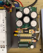
There are 2 adjuster knob type screws on the back of the Ksupply. 1 for voltage, 1 for current. Voltage is to be set at 8.1v and current to its maximum point. I did do the voltage accurately to 8.10v, but when I tried to move the current adjuster, it just kept rotating and rotating. It's a bad adjuster I think. So I set it to the middle-ish position and connected my kweld and Kcap to it. But now, the Kcap power LEDs, only the left of the 2 turn on. The manual indicates that insufficient voltage or current. Voltage is fine, it's the current for sure! Kweld at the same time shows 'insufficient battery" and shows voltage, 8.00v to 8.09v when plugged in, and falls slowly when disconnected.
I have contacted Frank also, I'll update with what he suggests. If anyone has had a similar problem and can help me, that would be greatly appreciated as well!
Cheers
I bought a kweld last year, but didn't get a chance to use it properly. I was using a cheapo lipo battery with insufficient power output. I was getting 750a max output from it and the weld were decent, but nothing good or promising. So I bought a Kcap and Ksupply to power the kweld. I received it day before yesterday and yesterday I was assembling it. I encountered a major problem.
There are 2 adjuster knob type screws on the back of the Ksupply. 1 for voltage, 1 for current. Voltage is to be set at 8.1v and current to its maximum point. I did do the voltage accurately to 8.10v, but when I tried to move the current adjuster, it just kept rotating and rotating. It's a bad adjuster I think. So I set it to the middle-ish position and connected my kweld and Kcap to it. But now, the Kcap power LEDs, only the left of the 2 turn on. The manual indicates that insufficient voltage or current. Voltage is fine, it's the current for sure! Kweld at the same time shows 'insufficient battery" and shows voltage, 8.00v to 8.09v when plugged in, and falls slowly when disconnected.
I have contacted Frank also, I'll update with what he suggests. If anyone has had a similar problem and can help me, that would be greatly appreciated as well!
Cheers
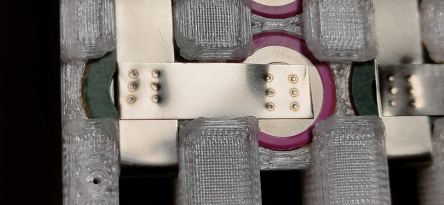
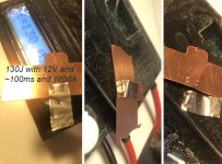
") Welded so that one electrod was in copper side and other in nikkel side.
Welded so that one electrod was in copper side and other in nikkel side.