Hi,
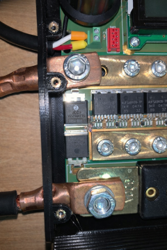
Can someone please explain to me why they’ve selected these particular Mosfets for kWeld?
So far I’ve seen in there:
1. Fairchild FDB0105N407L (discontinued now)
2. IOR AUIRFS8409-7P
There are 6 of them in parallel. People mainly seems to look at the max amp ratings in the datasheet BUT by looking at max SOA graphs, they BOTH should fail at given working conditions:
1. Drain to Source voltage = 12V (this is kWeld’s recommendation or 3s Lipo)
2. Welding time: usually the weld takes ~30-50ms (i know this device operates on joules rather then ms)
So: for a 30ms weld @ 12 volts we are looking at 2-3 Amps only if we want to operate within SOA even if there are 6 fets in parallel we’ve got ~20A max. Fairchild is a bit better as it indicates 6-7A but still we are light years from 2000A? They say in the datasheet 522A or 460A @ 10V BUT that’s for 10uS or 100uS ONLY not for times like 30ms+!!?? How does it even work without blowing the whole thing during the first shot? Could someone please explain this to me?
https://www.infineon.com/dgdl/auirfs8409-7p.pdf?fileId=5546d462533600a4015355b745e314f0