Latest road and single track weapon.

Kepler said:
In regards to fabrication, I have a hobby lathe with an overhead mill attachment and a variety of hobby quality tools and equipment. Nothing too special. However, being a Mechanical Engineer by profession, it allows me to design in a way that makes fabrication possible without the need for a lot of fancy equipment. Being able to visualize your design is very important when it comes to fabrication which is why i like to use drawing programs to model the design followed by mockups and finally the end product.
Hey John, seeing as you mentioned it, im about to buy a hobby lathe and vertical milling attachment.
Any suggestions? Im looking at this because its on a good special price from a physical shop.
http://www.paramountbrowns.com.au/hardware-machinery/products/machinery/metal-working/lathes-acc/metal-bench-lathe-350mm-bc-mini/
 
Hi PD. I think the mini is a little light on and you would be much better off spending an extra $400 and getting the next model up. Lathes need a bit of weight behind them for them to cut well without chatter. A 45kg lathe will work but it will mean small cuts and will limit what you can make. My lathe weighs about 150kg. Its a cheap chinese unit but it has done a heap of work and served me well. I have had it for 20 years and it cost me about $1200 back then.

You will need the 12mm tool set and also budget for a 4 jaw chuck if you can. Also suggest you budget for a dial indicator and digital vernier.

In relation to a vertical milling attachment, mine has sufficed but it is much nicer having the mill a separate machine. The cheap $600 unit will allow you fabricate most of the stuff that you need however, having some mass in the machine has the same advantage as with the larger lathe.
 
appreciate the info, for now that looks too big an investment. I think the main thing I liked about Kepler's battery boxes is one the alu tube which I have searched for ages but 50mm is not the dimension I'm after, more like really wide 120mm x 60mm...
More importantly the beautiful bends in the second box... the one I did the downtube was done so roughly with clamps and a mallet around the corner posts of our work bench, I know how hard it gets once the first few bends have been done, wondered how you bent it more than anything..

For me at the moment once I get my final battery specs worked out I want to just use base plates to save weight and then custom abs boxes which investing in the heat gun $80 is not to huge LOL

It's easy enough to bend, and layer with glue lots of thin sheets to build some complex stuff. I want to shift all the ca stuff to the top tube with custom stuff too... hate it up on the dash with all tons of wires needing to hang and turn with steering, not to fussed on seeing it much anyway..

3d printer in abs would be fun too if I had money to throw

oops off topic

cheers Kepler
 
Finally got some time to work on installing the 18650 cells into my custom battery box. Just to recap, the cells are LG 2850 mah from this thread http://endless-sphere.com/forums/viewtopic.php?f=31&t=61608

My configuration is 14S 4P which means 56 cells are required. Ended up buying 60 cells which came packaged up as per the picture below (10S 3P) x 2

Batt.jpg

First job was to break the packs down to individual cells. This required breaking off all the spot welded tabs so the plastic cell spacers could be removed. Was a bit disappointing having to break off all the spot welded tabs but unfortunately there was no other option if i was to squeeze 54 cells and a BMS into this battery box.

View attachment 7

Next step was to make sure 54 cells actually fitted including the BMS.

20141226_163718.jpg

Cells were then arranged as individual 4P 1S packs and parallel soldered using 3mm wide solder wick to bridge each cell

20141228_112114.jpg

20141229_164733.jpg

Of course soldering is not the ideal method of joining the cell however this was my only option if I wanted to build an 18650 battery pack. Each cell had the spotweld remnants ground off with a Dremel tool which also gave a roughened nice clean surface for the solder to stick too. Using an 80 Watt soldering iron, each cell was tinned with only a few seconds of heat being applied. Compressed air was then immediately blown on to soldered area to ensure all heat was quickly removed. After a quick blast with compressed air, the soldered area was immediately cool to the touch. The solder wick by nature solders with very little effort so it only took a quick touch of the soldering iron to attach the solder wick link to the battery. Again the soldered area was immediately cooled with compressed air.

Cells were hot glued and linked together in manageable sections with the 3 main sections joined and linked afterwards.

20141229_132229.jpg

20141229_153726.jpg

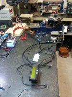
Before installing the BMS, I wanted to test out the pack and make sure it performed as expected. Also wanted to make sure the solder wick links were handling the current OK. Female 5mm bullet connectors were soldered directly to the positive and negative tabs of the pack and a 12 gauge power cable attached.

20141229_154042.jpg

Took the bike out for a quick 10km ride with a good mix of moderate to high power used. Removed the pack straight off the bike and checked all connections. Also used an infrared heat gun to see if there were any hot spots. Pack was an even 25 degC across every terminal and cell voltage had stayed nicely in balance.

So the job for tomorrow is to installed the BMS and charge port. Finally nearing completion. Certainly quite a labour intensive project but considering the results, I think it will be well worth it. I have been happy with 230 Whrs on this bike in relation to range and performance. Having 520 Whrs in basically the same package is going to be amazing.

20141229_164743.jpg
 
Kepler said:
Of course soldering is not the ideal method of joining the cell however this was my only option if I wanted to build an 18650 battery pack. Each cell had the spotweld remnants ground off with a Dremel tool which also gave a roughened nice clean surface for the solder to stick too. Using an 80 Watt soldering iron, each cell was tinned with only a few seconds of heat being applied. Compressed air was then immediately blown on to soldered area to ensure all heat was quickly removed. After a quick blast with compressed air, the soldered area was immediately cool to the touch. The solder wick by nature solders with very little effort so it only took a quick touch of the soldering iron to attach the solder wick link to the battery. Again the soldered area was immediately cooled with compressed air. Cells were hot glued and linked together in manageable sections with the 3 main sections joined and linked afterwards.
Hey, thanks for the details & pics on your method. Like to compressed air cooling trick and use of solder wick. FYI, placed in my Imaginarium.
 
Love it! This is how I might end up doing mine, so I'm really glad you posted these pics. Very handy!
 
Kepler, I see that you were a fan of front handlebar mounted battery packs previously (using a Topeak handlebar bag). I am building a full suspension bike for mild single track riding and was wondering if you could tell me what handling differences you experienced now that you have switched to a "triangle mounted" battery setup. The bike I am building just barely has room to possibly squeeze one of Em3ev's triangle batteries in the frame, but it will be tight. Using a handlebar bag for the battery (8 pound battery) would be much easier, but I would rather not do that if it will have a large negative impact on the handling. The Em3ev rectangle battery will not fit in my triangle, and the triangle battery will not fit in the Toppeak bag, so I have to make a commitment as to which method to use before purchasing the battery. I would appreciate it if you could share your experiences and opinions about these two types of battery mounting methods for a trail riding bike.

Thanks,
Lorrin
 
Decided it was time to have another go at interfacing a Cycle Analyst to a Bafang BBS02 and ditch the useless stock display.

Result? Nice uncluttered Handlebars, and a fully functioning CA that interacts with the drive seamlessly.
 

Attachments

  • 20150309_173746.jpg
    20150309_173746.jpg
    100 KB · Views: 10,645
  • 20150309_162743.jpg
    20150309_162743.jpg
    93.6 KB · Views: 10,645
Two approaches have been used for this conversion.

The first approach is strip down the stock interface display to its its bare circuit board, heat shrink it, and mount it somewhere off the handlebars. This has the advantage of still having the stock controller buttons to turn the drive on and off and to set the level of assist.

Custom programming of the drive is not necessary with this method which can be an advantage if you don't have programming capabilities.
The Cycle Analyst now has full control of the throttle and levels of throttle assist and speed limits while under throttle control.
The cycle Analyst will switch on and off with the stock button on/off control including auto power down.
The Cycle Analyst picks up speed sensor output from the Bafang speed sensor.
The custom shunt measures real current draw and as such you get all cool display readings we have come to expect from a full feature ebike computer.
Below is the wiring diagram for the first method of conversion. Note the diode connected in-line with the throttle override input to CA. This is necessary for the throttle override feature of the CA to work correctly.


The second approach deletes the stock display / interface completely. This method reduces the ability to set multiple PAS levels however it does still provide you with 1 PAS level and the ability turn PAS off on the fly. Levels of throttle assist are fully adjustable through the CA.
It is necessary to have custom programming capabilites if you decide to go down this path.

I presently have the bike set up in this configuration. I have the PAS programmed to a conservative 250W and a push button capped at 550W. I also have the gear switch micro that kills PAS (and throttle) when activated.

More to follow on this one.
 
I've been wondering about this - nice explanation Kepler!
 
Nice work !

i would like to make something similar, what custom Shunt did you use ? and where did you buy it from ? i want a nice small compact one that is for like 50 amps or less like you have.

Also where do you go those plugs that 6 pin CA plugs ?
 
Outstanding! Glad to see that you got this working - well done. :D

A small point with regard to the diode:

This should only be required for CA V2 with pre-revision 11 PCBs. Those earlier units have no diode on the ThO line. Later V2 units as well as the V3 have both straight-out and diode-out PCB pads. Here's an output pad summary - your configuration uses the setup in the "Output with diode" column. I'm guessing you have an earlier PCB which is why you needed the external diode.

CA-Throttle-Output-By-Rev.gif
Here's some PCB details...

CAThrottleOutputByRev_2.png
So - I think folks duplicating your efforts may be able to select a different output pad in lieu of the external diode if they have a V3 or later V2. On the other hand, all versions will work fine even if an external diode is added and there is already an internal diode (2 diodes in series).
 
Thanks for the clarification Tek. I am using a CA-RC version CA on this bike which is very similar to the CA V2 Rev11. I didn't realize there was a second throttle Pad that I could have used without a diode. Thanks for the headsup. :)

As a quick update, I have been using the drive with the CA only using the CA's current control. It has been operating perfectly with the CA having no problems at all controlling current through the CA's throttle override feature.

Differences between my last CA conversion effort and this effort:

Letting the drive's inbuilt controller take care of PAS duties. The BBS has really nice speed PAS control logic so best let it continue to do so.

Programming the drive in Throttle current mode instead of the standard throttle speed mode. The power delivery through the throttle is far more linear in Current Mode and as such this allows the CA to do a better job at controlling the drive in smooth and predictable manner.

I will get the wiring diagram and controller setting posted up tomorrow.

I plan to also add a remote pot to the CA so I can set throttle max current on the fly.
 
Clocked up a few hundred km on CA only control. Very happy with the overall performance of the set up. This will be a keeper :)

Below is the wiring diagram for the conversion including the additional control for PAS cut and fully variable throttle current adjustment on the fly.

CA2 BBS02_2.jpg

However, for the above to work effectively, some custom programming is required.

Please pay special attention to the throttle tab settings. The Throttle mode and %start current are especially important. %start current can be set from zero to 5. I have set mine to 3 because I like the throttle to just engage when I hit the gear change PAS cut. It keeps the chainring idling and allows me to still change to a higher gear while I am coasting (not pedalling).

With the settings below, I have one level of PAS set 250W and fully variable throttle from zero to 800W. I have capped my max Watts at 800W due to the type of batteries I am using. Typically I have my throttle current wound back to 500W which i find to be plenty for this bike.

JW Bafang settings Standalone CA2_1.PNG

BBS_CA_Prog2.JPG

View attachment 1
 
Below is the handlebar layout with the standalone CA setup.

Note the adjustment knob on the right hand side. This allows me to limit throttle only Watts. Range is from 100W to 800W. Very easy to set on the fly. Loving this setup. Very few negatives in relation to operation. It would be nice to have an adjustable PAS level on the fly also however 250W is a nice economical level of assist and if I want to run with mor assist, I just hold the throttle button down and set the level of assist via the Watt limit Potentiometer.
 

Attachments

  • Handlebar layout.jpg
    Handlebar layout.jpg
    91 KB · Views: 10,314
Some, please configure this cable. Begging...
I'd leave the version leaving the Bafang display in heat shrink, I think.
I need and use more levels of assist. Unless I'm not grasping the setup.

Another Kepler masterpiece. Well done sir!
 
Great stuff info,

I got very excited seeing you are able to get rid of the stock display completely.

I don't care about using the ca or pas for it either, wonder if you have worked out how to wire/programme an on/off switch and throttle only directly to the controller.

cheers
 
tomjasz said:
Some, please configure this cable. Begging...
I'd leave the version leaving the Bafang display in heat shrink, I think.
I need and use more levels of assist. Unless I'm not grasping the setup.

Another Kepler masterpiece. Well done sir!

Thanks Tom.

Heat shrinking the display is a good option if you want to keep levels of assist still adjustable. You are grasping the setup 8) .
 
John Bozi said:
Great stuff info,

I got very excited seeing you are able to get rid of the stock display completely.

I don't care about using the ca or pas for it either, wonder if you have worked out how to wire/programme an on/off switch and throttle only directly to the controller.

cheers

Thanks John,

What you are asking is very easy to do. Below is a diagram on how to do this. Again it is important to have programming access to the drive for this mod to work at its best. Use the same programming as I used for the stand alone setup but change "Designated Assist" to "0" or "1" to stop the PAS working and set "Start Current(%) to "0"
 

Attachments

  • BBS02_Throttle_Only.jpg
    BBS02_Throttle_Only.jpg
    24.5 KB · Views: 10,269
You are a legend Kepler.

Thanks. :D

I need to get myself a programming cable and another on off switch... The standard hold 3 seconds one I guess would not work right?

edit: Do I need to open the motor up and get to the controller to have programming access or is it a matter connecting "prog" wire to a USB plug to a computer with the correct programme?

What will happen if the programming is not done? Automatic pas level 1?

cheers my to do list is growing.
 
The standard switch definitely won't work. You just need a nice quality compact on off switch.

No you don't have to open up the motor. you just need to sacrifice your harness that goes between your your drive and handlebar equipment. Or you can buy a new harness from here http://www.empoweredcycles.com/prod...-electric-bike-kit-replacement-wiring-harness to modify.

If programming isn't done, PAS will stay active but on one setting. Throttle won't have a very linear feel to it.

In regards to programming, you need to go to the Bafang programming thread to understand what is involved. A bit of light reading for you :) http://www.endless-sphere.com/forums/viewtopic.php?f=28&t=58780
 
On a different note, how is this for good bike security at the office. :lol:

20150325_131151.jpg

The office building I work from is a heritage listed old bank. The strong rooms in the basement were converted to bike parking to improve the building's overall GreenStar rating. Now that is what I call bike safety. :mrgreen:
 
Very secure, wish I could park my bike at work. Only place for free has sun all morning and rain if its windy....

subscribed that topic but man - light? I got though 5 pages from page one, then skipped to work backwards a few pages till I fell asleep.
I will hopefully get the ttl usb donga from emax Sydney. waiting for a reply, so until all my parts arrive:

Is it ridable? without programming? You say not very linear. What it's like jerking more amps less amps more amps less amps? or do you mean it accelerates as stock? I just want to know it's ridable because I plan to do a temporary wire chop today until parts arrive.


I don't know if my throttle is elcrapo or not but I can't feel more than throttle is on or off, with no grade between it. I don't care either as all I will use the bafang for is throttle from 0-8kmh. 10kmh is unloaded 44t-48t rear.

Is it possible to use the same on off switch as I use for my infineon? so it on will power up both motors or would there be other problems arrising?
cheers.
 
Back
Top