Liitokala 20s 72v 90a

martinev

10 W
Joined
Jun 24, 2022
Messages
89
Hi all. Advice needed.I have removed our BMS from our battery because it would not charge and I was getting no voltage from the plug with my meter.so we split the battery open and if I use my fluke across the earth black into the BMS and one of the red positive wires we get 80v from battery wires. But if I connect the fluke to the 2 black wires coming out of the BMS that got to the charging plug and main plug I get no voltage reading. So the I checked the temp sensor and that works fine cutting in and out using a heat gun to simulate over heating. If I wanted to change type of BMS do you have to change over and solder all the new wires on for the sensors. I can get one exactly the same but it's 2 weeks. Thanks for any advice given 👍
 

Attachments

  • IMG_20230419_192701.jpg
    IMG_20230419_192701.jpg
    946.6 KB · Views: 2
If you want to change the model of BMS, it may have the same connectors (that Molex sort, not sure of the name but they’re pretty standard across BMS platforms) in which case you can just insert the current balance connectors. If not, you could either re-solder the connections at the BMS end or the battery end of the balance wires. If you replaced with this, for example:

8bc0918e-332a-4e8a-8472-3a8c5cd28e94-png.332992


As you can see the connector count on either side is a bit different so you could redo the connections at either end, whichever is easiest for you. If you are going to switch the BMS, I have heard many good things about the QUCC brand pictured, they’re said to be reliable and high-quality, with an app for connecting via Bluetooth to monitor and adjust a fairly comprehensive range of settings.
 

Attachments

  • 8BC0918E-332A-4E8A-8472-3A8C5CD28E94.png
    8BC0918E-332A-4E8A-8472-3A8C5CD28E94.png
    3.8 MB · Views: 78
Thanks for your reply. This is the board I can't see any issues that would prevent it completing the earth though the BMS and out to the black wires and the charge and main plugs ?
 

Attachments

  • IMG_20230420_182253.jpg
    IMG_20230420_182253.jpg
    1.1 MB · Views: 5
Last edited:
Have you checked all 20 group voltages? Depends on BMS specs, but they all need to be above 2,9 volts to allow charging.

If you find one at 2.8 and the rest are higher, you could get a single charger and try to bring that cell close to the others.
 
hi docw009
surely wouldn't there would still be a voltage at the plugs after the bms ?,
or are you saying low voltage cells the bms would stop any voltage passing though it ?
thanks
 

Attachments

  • IMG_20230419_192701.jpg
    IMG_20230419_192701.jpg
    946.6 KB · Views: 2
In this thread you mention the system was cutting in and out
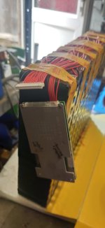
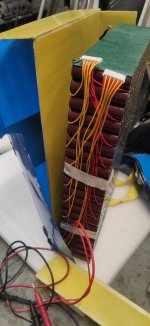
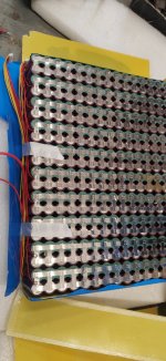
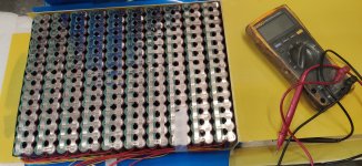
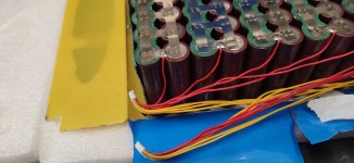
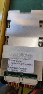
which usually indicates a problem with one or more of the battery cells, so that the BMS turns off the output to protect the cells from overload or overdischarge. Sometimes that shows 0V, if it's well designed, and sometimes it shows a small voltage because of leakage current from the more common cheap designs.

If a cells actually drop below the safe recharge limit (somewhere around 2.8-2.9v or less), it will also turn off the charge port as well as the discharge port.

In that case, your BMS is doing exactly the job it is there to do.

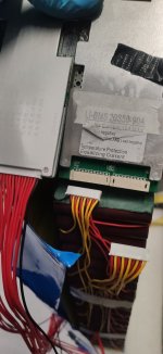
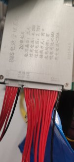
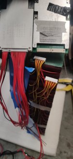
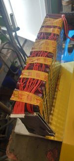
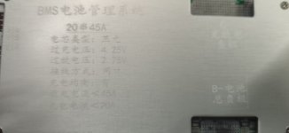
You should test each of the battery cells (or groups of parallelled cells).
--Set your multimeter to 20VDC, with the red lead plugged into the VDC plug of the meter, and the black lead in the ground or common plug.
--Put the black leads' other end on the most negative cell terminal (not the wires, the actual cell metal).
--Put the red leads' other end on the positive end of that cell (the actual cell metal).
--Note that voltage down in your post.
--Move the black lead to where the red lead is.
--Move the red lead to the next cell's positive.
--Note that voltage down in your post.
--Repeat this until you have measured every cell (group) in series of the pack. If it's a 20s pack, you will have 20 voltages. Etc.

Then we can see if any cells are different from others, which indicates a problem with them (they should all be exactly the same), and especially if any are below safe recharge limits, etc.
 
Yes it's 20s pack ok I will check each parallel group. The cutting out was corrected by reducing the draw to 50amp in the controller. The small 20ah was cutting out when trying to draw over 60amps so that seems to be ok now we have lowered the amps.. Bike nearly finished see pic
 

Attachments

  • IMG_20230421_190118.jpg
    IMG_20230421_190118.jpg
    1.6 MB · Views: 2
  • IMG_20230421_190109.jpg
    IMG_20230421_190109.jpg
    3.5 MB · Views: 2
  • IMG_20230421_190148.jpg
    IMG_20230421_190148.jpg
    3.9 MB · Views: 2
I have purchased this just in case it is the BMS. I think this is of similar spec.
 

Attachments

  • Screenshot_2023-04-22-09-12-41-161_com.ebay.mobile.jpg
    Screenshot_2023-04-22-09-12-41-161_com.ebay.mobile.jpg
    528.8 KB · Views: 2
I have purchased this just in case it is the BMS. I think this is of similar spec.
Just a thought, but I would strongly recommend never getting anything for your EV that you are not *certain* is the correct specs for the other parts you have on it.

Getting things that you're not sure match your other parts leaves you with the chance of overloading your system, and with a BMS that is there to protect your cells from the potential for a fire....I would not take the risk that it is not correct.
 
yes i totally understand your point amberwolf,
and i agree if your anyone is not from a electrical / engineering background ,

this unit 20S 72V 45A Li-ion Battery Protection Board
is a better match for us, as we reduce the amps drawn from other battery within the settings in the kelly controller,
so our range would be better and a better setting for the switching over to the 20ah battery, thanks
 
Hi amberwolf
can you explain please how to test the battery pack groups.. Here are my photos of the battery open and my new BMS . Thanks amberwolf
 

Attachments

  • Screenshot_2023-04-25-20-39-23-666_com.ebay.mobile.jpg
    Screenshot_2023-04-25-20-39-23-666_com.ebay.mobile.jpg
    454.8 KB · Views: 1
  • IMG_20230425_190232.jpg
    IMG_20230425_190232.jpg
    760.6 KB · Views: 1
  • IMG_20230425_190459.jpg
    IMG_20230425_190459.jpg
    1 MB · Views: 1
  • IMG_20230425_185707.jpg
    IMG_20230425_185707.jpg
    3.2 MB · Views: 1
  • IMG_20230425_185715.jpg
    IMG_20230425_185715.jpg
    2.8 MB · Views: 1
  • IMG_20230425_065237.jpg
    IMG_20230425_065237.jpg
    2.9 MB · Views: 1
can you explain please how to test the battery pack groups..
What specifically do you want to test for? Need to know that to give specific instructions.

Instructions for every possible test would be book-length, and you'd just need to research that in the many many threads on battery builds and testing and repair. ;) (cuz I don't have enough time to research and write that all out in the next few months or more)
 
hi amberwolf
well like you said i your post the cell packs ! before i change the bms it would be good to check all i can while the pack is apart
a simple diagram or draw on the photos i sent, cheers
 
If you mean in this post
it already has the instructions, step by step.

If you mean some other post you'll need to link it or quote it.
 
I'll see if I can find a fault Thanks
 

Attachments

  • IMG_20230421_190148.jpg
    IMG_20230421_190148.jpg
    3.9 MB · Views: 1
So this the new replacement BMS I can see some locations on the new unit ie B20 runing down to B2 B1 then B- on the aluminum cover and are mainly red wires apart from 2 black wires. Now the original BMS has 2 plugs the same size and red and yellow and 1 black wire but no locations markings on the old BMS.. How do i know which is B1 and B20 on the battery cells?. If I test each cell pack from the yellow and red wires in the 2 plugs they go up in 4v increments to 40v . What's the best way to change over the BMS unit? Thanks
 

Attachments

  • IMG_20230427_180947.jpg
    IMG_20230427_180947.jpg
    860.5 KB · Views: 1
  • IMG_20230427_180935.jpg
    IMG_20230427_180935.jpg
    688.6 KB · Views: 1
  • IMG_20230427_180903.jpg
    IMG_20230427_180903.jpg
    754.9 KB · Views: 1
hi I like to thank amberwolf
i removed the old BMS unit today and reordered a new unit in
and then re shrunk wrapped the battery,
so thanks again for your help
 
hi amberwolf , just like to say thank you for your help and advice, i checked all 20 celes groups all good
so i changed over the bms over battery all good now, thank you
 

Attachments

  • IMG_20230508_120648.jpg
    IMG_20230508_120648.jpg
    669.1 KB · Views: 1
  • IMG_20230508_120651.jpg
    IMG_20230508_120651.jpg
    516.8 KB · Views: 1
  • IMG_20230505_144603.jpg
    IMG_20230505_144603.jpg
    4 MB · Views: 1
also if anyone is interested
we are now offering a swing arm fabrication and supply for the large frame Lambretta and large frame Vespa.
and we can also custom build, and will post world wide,
see photos
thanks
 

Attachments

  • arm.jpg
    arm.jpg
    759.7 KB · Views: 0
  • IMG_20221118_105402.jpg arm vespa.jpg
    IMG_20221118_105402.jpg arm vespa.jpg
    931.3 KB · Views: 0
Back
Top