• Hello ES! We could use some help to get us past the finish line on building the new knowledgebase for the forum.
    Can you donate? Please see our fundraising page. Thank you!

Lishui LSW1702-1F STM32FEB Help with torque sensor connection

mhmt

New here
Joined
Jul 8, 2026
Messages
15
Location
Türkiye
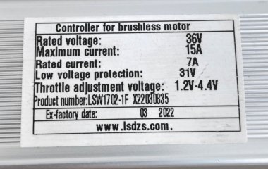
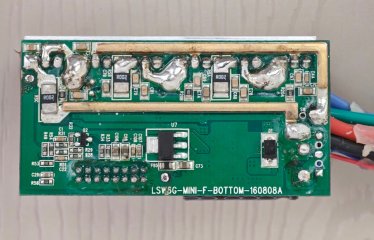
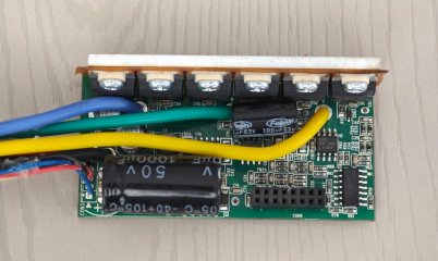
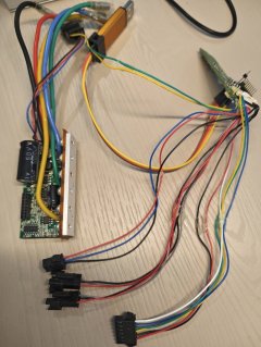
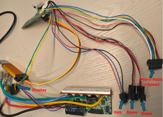
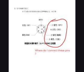
Hello, I want to connect my torque sensor to the motor controller shown in the photos. My electronics knowledge is limited, but I have a multimeter. How can I wire the torque sensor? I've already sorted out the software side, I just don't know how to make the physical connections.

Screenshot_2026-07-10-15-21-11-913_com.miui.gallery-edit.jpgScreenshot_2026-07-10-15-19-03-680_com.miui.gallery-edit.jpgScreenshot_2026-07-10-15-18-49-194_com.miui.gallery-edit.jpgScreenshot_2026-07-10-15-18-18-082_com.miui.gallery-edit.jpgScreenshot_2026-07-10-15-18-35-344_com.miui.gallery-edit.jpgScreenshot_2026-07-10-15-32-02-570_com.miui.gallery-edit.jpgScreenshot_2026-07-10-15-16-16-158_com.google.android.apps.docs.jpgScreenshot_2026-07-10-15-15-49-452_com.google.android.apps.docs.jpg
 

Attachments

  • Pinout Old Generation.PNG
    Pinout Old Generation.PNG
    245.2 KB · Views: 4
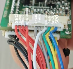
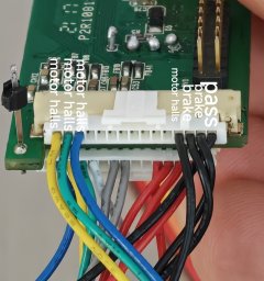
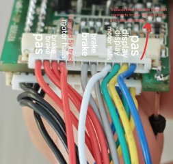
Strange, that's the first Lishui controller that I see, where the connector pins are not labelled properly on the PCB. Perhaps you can mark them as good as you can on a photo on basis of the wires with obvious functions.

1783689817065.png

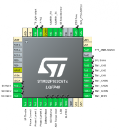
So you have to identify the pin SP (Throttle) and/or AD1 (Torquesensor) on the remaining pins of the header. Both will have 0V to GND when the controller is switched on. If you check, which of the remaing pins are GND and 5V supply, there are not left many candidates, I guess.
 
Last edited:
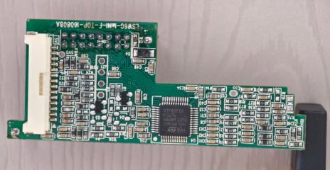
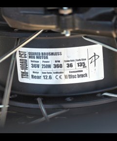
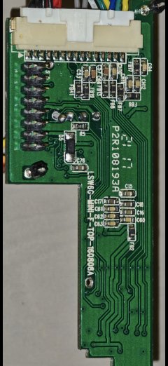
I replaced my motor with a TBK-100AD CST. My current controller has a speed limit, and the speed doesn't exceed 12 km/h. I couldn't solve the issue through the display settings. My display uses UART Protocol 2. I bought the LSW controller from a seller who deals in unclaimed customs goods. Luckily, there was no epoxy potting inside. The circuit board is in two pieces. The board housing the chip has 14-pin and 15-pin sockets, and half of them are empty. I figured I could connect my torque sensor to the empty pins. As you mentioned, there are no descriptive labels or markings on the board.Screenshot_2026-07-10-16-17-40-191_com.miui.gallery-edit.jpgScreenshot_2026-06-21-20-04-19-880_com.miui.gallery-edit.jpgScreenshot_2026-06-22-21-36-02-820_com.miui.gallery-edit.jpg
 
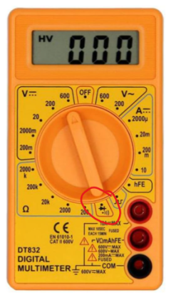
Identify the pins with GND and +5V supply first by a continuity test of the red and black wires of the PAS connector. Then search the pins with 0V on the remaining unidentified pins (see updated post above).
 
Strange, that's the first Lishui controller that I see, where the connector pins are not labelled properly on the PCB. Perhaps you can mark them as good as you can on a photo on basis of the wires with obvious functions.

View attachment 390333

So you have to identify the pin SP (Throttle) and/or AD1 (Torquesensor) on the remaining pins of the header. Both will have 0V to GND when the controller is switched on. If you check, which of the remaing pins are GND and 5V supply, there are not left many candidates, I guess.

Does the blue wire go to the AD1 pin?
 
Which blue one, there are many blue wires ;) Blue on the three pin JST SM connector is PAS1, TA (PB8)

I bought the LSW controller from a seller who deals in unclaimed customs goods.
Do you have a link? This seems to be an intersting controller (y)
 
Last edited:
Hm, this item is not available in Gemany. :(
Sadly most ebike parts are geo fenced for Germany meanwhile, I guess I would have to use a VPN to turkey :)
No products are coming in from abroad to Turkey anymore. To bring anything in, you have to go through official import procedures. There are a lot of expenses and legal obligations. Someone else bought it, but it got stuck at customs. Then another person bought this product from customs through an auction. They put it up for sale from within Turkey. That's how I was able to get it
 
Identify the pins with GND and +5V supply first by a continuity test of the red and black wires of the PAS connector. Then search the pins with 0V on the remaining unidentified pins (see updated post above).
I couldn't do it. It turns out I don't have the necessary electronics knowledge. I don't have enough background to figure out something new. I couldn't identify the circuit board. However, if there were a step-by-step guide, I could get this done. Thank you for the software. I assume the Java interface is your design.
 
Don't you know google translate?!
1783789632509.png
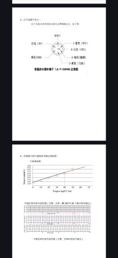
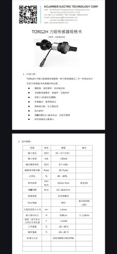
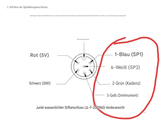
You need only 4 wires of the 6.
- GND
-5V
- 2-Grün (Kadenz)
- 3-Gelb (Drehmoment)

controller --> torque sensor:
GND --> GND
5V --> 5V
TA-PAS --> 2-Grün (Kadenz)
AD1 -->3-Gelb (Drehmoment)

Have you identified the pins with 0V to GND whithin the unused pins on the header that are not GND nor +5V?
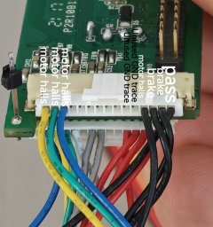
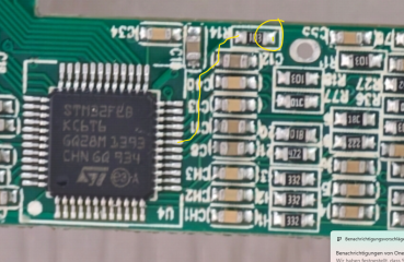
One of them is AD1. As the PCB is not potted, it should be quite easy, to follow the traces from the PB1 (AD1) pin of the processor to the header. There will be a resistor in the path, as far as I can see from your photo, you should test the continuity from the the marked resistor pad to the connector with your multimeter in "beep" mode.
1783790658456.png

1783790387511.png
 
Last edited:
Don't you know google translate?!
View attachment 390362
You need only 4 wires of the 6.
- GND
-5V
- 2-Grün (Kadenz)
- 3-Gelb (Drehmoment)

controller --> torque sensor:
GND --> GND
5V --> 5V
TA-PAS --> 2-Grün (Kadenz)
AD1 -->3-Gelb (Drehmoment)

Have you identified the pins with 0V to GND whithin the unused pins on the header that are not GND nor +5V?
One of them is AD1. As the PCB is not potted, it should be quite easy, to follow the traces from the PB1 (AD1) pin of the processor to the header. There will be a resistor in the path, as far as I can see from your photo, you should test the conductivity from the the marked resistor pad to the connector with your multimeter in "beep" mode.
View attachment 390364

View attachment 390363
Thank you very much. I didn't even know how to do this. I have identified two empty GND traces and one 5V trace using the multimeter's continuity mode. I will try to determine the AD1 and TA-PAS pins using the method you suggested. I am learning this alongside you.
 
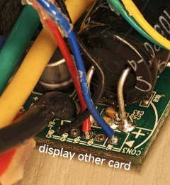
I traced the AD1 Torque Input pin. It goes to the 01C resistor. From there, it goes under the board. After going under the board, it leads to a component marked C40, which I think is a capacitor. I couldn't trace it any further.IMG_20260712_233453.jpg
 
How can I follow the trace
Often there is just one hardware filter (resistor in the track + capacitor to GND) so you can just check if you find a direct continuity from the resistor pad to one of the header pins.
If you don't have success, try to search for a tutorial on YouTube e.g., how to follow tracks on a PCB. But this PCB looks so tidy and simple, that you should manage it yourself quite easily.
 
Often there is just one hardware filter (resistor in the track + capacitor to GND) so you can just check if you find a direct continuity from the resistor pad to one of the header pins.
If you don't have success, try to search for a tutorial on YouTube e.g., how to follow tracks on a PCB. But this PCB looks so tidy and simple, that you should manage it yourself quite easily.
IMG_20260714_211816.jpg
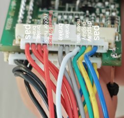
As far as I could trace, I found the input next to the brake inputs. I hope it's the right one. I am going to connect the PAS cables + the input I found to the torque sensor and give it a try. I hope it works.
 
Back
Top