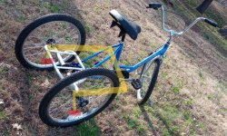
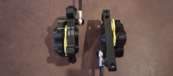
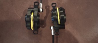
Thanks. I'm still fuzzy on how everything is supposed to bolt together. I have robotics experience and a TIG welder so I understand gear ratios and programming and general mechanical principles. But the last time I rode a bike, V brakes were a brand new thing and I didn't have them. So the only thing I know about modern bike parts is what I can read online. No hands on experience, except these disc brakes literally in my hand, no rotors.
The info there is not the most up to date, but you may find Sheldon Brown's bicycle maintenance site useful. I learn something new just about every time I go there to look something up for someone here, and I've been doing that for at least a decade and a half.

Q. What is the BCD Bolt Circle Diameter of 6 bolt 180mm disc brake mounts? Is that standardized?
All the typical bicycle brake rotors and hubs are ISO standard spacings (though not all use the same outer diameter; you may find 200mm rotors, and 203mm, etc, as well as smaller ones)):
Q. Do any bike compatible rotors come with a 2.5" BCD compatible with go kart hubs?
Probably not: A few seconds on google image search shows a lot of possible shapes and styles for go-kart rotors, some of which have keyways and / or grub screws, some of which have bolt holes, some of the latter have four holes, some have other numbers.
But if the go-kart rotors are the same thickness as the bicycle rotors (you'd have to check), then you just use the calipers you have and get whatever rotors fit whatever hubs you're using.
Another few seconds shows there are adapters for certain combinations of hardware; I don't know if any of them will do what you want:
I required amberwolf's explanation to visualize how flipping the same caliper backwards and upside down for the other wheel is equivalent from a lateral spacing and pad angle perspective. However now the banjo is at the bottom
Then don't put it at the bottom

, rotate it so it is in the right place for your application. It doesn't matter where the caliper is on the round rotor, as long as your mount transfers the forces to the frame correctly, it's doing the same thing to the rotor no matter where it is (remember the rotor is spinning, and has no idea "where" it is relative to the caliper, and vice-versa).
The only time a specific caliper orientation is required relative to the rotor or frame is when you have a frame that is already built in some way with mounts in some specific place. If you're building the frame "from scratch" like this, you figure out where you want the calipers, and design the frame with mounts to do that.

which is a bad thing AFAIK because any air in the line will get trapped at the piston rather than bubble up to the master cylinder. Result sponge pedal... er, lever. Just applying what I know about car brakes. Does that happen?
Don't know--I don't use hydraulics because of all the various problems they can have, most of which can't be fixed roadside without stuff I wouldn't want to be carrying with me all the time.
Every problem I've ever experienced wiht cable-operated brakes I've been able to deal with roadside in a few minutes and be back on my way, so I stick with those, since they are strong enough to brake my trike just fine (so were the rim brakes before that, but after I broke a fork and had to temporarily go to a fork with no rim bosses I tried the Avid BB7 and they work just fine so I stayed with them).
So wondering what is meant by "mounting one of them in front of the rotor and one behind". Changing the angle fore or aft doesn't seem like it would make any difference. Do you mean leave the left caliper in the exact same orientation as the right, with both banjos/lines exiting front left of the calipers and both facing the left wheel? If so the left wheel would need the caliper mount somehow between wheel and rotor. I don't see how that is possible.
Assuming you are mounting these inboard of the wheels, then each caliper mounts "facing" the centerline, away from the rotor, wheel, etc. It's rotation relative ot the other makes absolutely no difference--each one is independent; that was my point about them not needing to be mirrored in your case.
It's probably easier to visualize if you setup a simulated frame (sticks, wood, carboard, whatever) and wheels and rotors in place on it, and set the calipers on the rotors, moving them around until each one is in a compatible place with your needs and cable routing, etc. Then design the mounts for the frame so they end up there.
If you cannot find a position for each caliper (independent of the other) that works for your setup, then you'd need a different caliper to fit that setup.
How are the Avid BB7 simpler to install? Just because they are not hydraulic? Or are they able to be taken apart and reconfigured for a true mirror arrangement?
Just because they're cable-operated, so you can do whatever you want with them as long as the cable routing works out for you. No worries about folding/crimping a hydraulic hose, or having one so long that it has so much volume that the lever can't produce enough pressure change to make it work correctly. I think I might have 10 or 12 feet of cable between my lever and my caliper on the Avid BB7, because of the long steering tiller on SB Cruiser, and the brake still operates fine, with as fine a control over it as I need while still having full braking power (enough to skid the wheel) available too.
My limited understanding of ebike motors is that the slope of their torque curve does not reach the upper left corner of the graph like brushed motors do, but levels off near zero RPM.
Some ebike motors are brushed, too, so I'm not sure what you mean.
If you want to see how the torque curves for various motors work under your specific conditions, with various voltages, currents, etc. I recommend playing with the motor simulator at ebikes.ca . I don't think any brushed motors are listed there to compare with, but if you already have torque curves for some, you can setup the simulator for the same conditions and voltage and current as those curves you have, and try different motors there to compare.
(if you don't use the same conditions, etc., you can't directly compare the results).
Note that a brushed motor does it's own commutation, so it controls it's own startup and rotation based on the voltage applied across it and the current available to it from whatever controller is used (if any).
A brushless motor is commutated by the external controller electronics, which also control the voltage and current, so how that controller is designed and/or setup/programmed determines how well that commutation, startup, and rotation is done under any particular condition.
It's more difficult to setup and tune a brushless system for that startup situation and fine low-RPM-under-load condition than it is to do the same for brushed motors, so for your application the brushed motors would likely be simpler to deal with.
Your only real issue is likely to be chain slop if using a chain-driven (or belt) system, but tensioning systems (slots in the motor mounts, for instance) can take care of that pretty simply.


