mid drive project for pikes peak

Warren said:
Len,

"I am pretty sure both fixed and frewheeling cogs on the hub motor are going to be 14"

That won't work. Smallest standard freewheel is 16 tooth.

Warren


Good catch. forgot that - went into the bike room an both were 16t freewheels...So the config will be 50t/16t crank to freewheel on middrive, and then the orginal config for the drive chain cog to rear wheel. This will give me a bit more cimbing capacity anyway.....


Len
 
Warren said:
Len,

"I am pretty sure both fixed and frewheeling cogs on the hub motor are going to be 14"

That won't work. Smallest standard freewheel is 16 tooth. There used to be a 15 tooth made, where the cog was outboard of the freewheeling mechanism, but they are no longer made. There are 14 tooth freewheels made in the smaller metric BMX thread size.

Warren
They seem to have old stock of the AC Racing 15t, which Warren refers to, here: http://americancycle.com/product/ac-race-888-freewheel-1984.htm Cheap, too!
 
Although I have never actually tested my cadence, my gearing dictates around 120the or just below depending on the actual loaded rpm of the motor and its totally comfortable foe me at all but totally WOT top speed... might be easier to gear closer to mine ..
 
You inspired me, I ordered a few things to get ready to do something similar to your idea, with a little twist, bit it should haul the mail pretty well I think with a couple thousand watts on tap... obviously, I will dial it back for the race though...
 
"They seem to have old stock of the AC Racing 15t"

Dang! Very cool. I may have to order some.

"comfortable for me at all but totally WOT top speed"

I ride at WOT all the time. That is what the gears are for. If you gear so you are at a comfortable cadence at WOT, it is more efficient running the controller at 100%. If you want to go slower, or draw fewer watts, just downshift, if you want to go faster, or pull maximum power, just upshift.
 
Actually, in my findings, about 80-90% throttle is the most efficient, IF you have the motor spinning around the same percentage of its max RPM. Throttle does not dictate efficiency so much as the motor RPM, at least that was the case with my R/C bike...
 
whadiddja get?


I was thinking about the carrier for the freewheel+fixed cog, and how to join it to the existing right hand threads on the freewheel cover plate. Seeing how this could be adpated to just about any hub motor for a mid drive conversion, it might be worth while to design and fab up a dozen or so.

Anyway, I think the easiest way to do this is to basically create a thread on coupler that allows one to screw in an additional length of right hand threaded, thick tubing/axle used as a carrier hub. After joining the cover plate to the threaded carrier hub with the coupler, one could the simply thread on the freewheel + fixed cog (with lock rings on either side),and perhaps even insert a cartridge bearing in the end (opposite the cover plate) to distribute the loading forces on the carrier hub itself.

If the forces of the hub motor on the fixed cog driving the rear wheel would cause it to unscrew the carrier hub from the coupler, the perhaps the carrier hub gets threaded half - right hand, and half left hand, respectively so the forces of my pedaling efforts & the the forces of the hub motor actually serve to tighten each cog appropriately.


Does this make sense? Need the folks that see this tuff better than I do to impart their wisdom.....

len
 
"Actually, in my findings, about 80-90% throttle is the most efficient, IF you have the motor spinning around the same percentage of its max RPM. Throttle does not dictate efficiency so much as the motor RPM, at least that was the case with my R/C bike..."

I don't understand how running the controller at 80-90% throttle could be more efficient than running it at 100%. I have my motor geared to my cranks so that at WOT I am spinning at 80 rpm cadence, at the motor's most efficient rpm, according to the motor manufacturer's spec sheet. If I gear down so I can spin faster, the motors efficiency drops, and my average speed drops. My Wh/mile will go down, because the motor's watts will go down, but a higher percentage of those watts are wasted to heat. If I gear up to spin slower, the motors efficiency drops, and my average speed goes up. My Wh/mile will go up because the motor is doing more work, but it is also wasting a higher percentage of those watts to heat.
 
Warren said:
"Actually, in my findings, about 80-90% throttle is the most efficient, IF you have the motor spinning around the same percentage of its max RPM. Throttle does not dictate efficiency so much as the motor RPM, at least that was the case with my R/C bike..."

I don't understand how running the controller at 80-90% throttle could be more efficient than running it at 100%. I have my motor geared to my cranks so that at WOT I am spinning at 80 rpm cadence, at the motor's most efficient rpm, according to the motor manufacturer's spec sheet. If I gear down so I can spin faster, the motors efficiency drops, and my average speed drops. My Wh/mile will go down, because the motor's watts will go down, but a higher percentage of those watts are wasted to heat. If I gear up to spin slower, the motors efficiency drops, and my average speed goes up. My Wh/mile will go up because the motor is doing more work, but it is also wasting a higher percentage of those watts to heat.


OK I agree with that, that's the most important part.....
 
SOLVED!

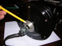
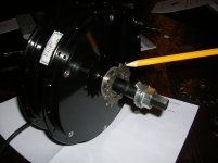
With regards to desiging & fabricating a hub carrier that can accommodate a free wheel + fixed gear so that he free wheel is driven by the mid drive, and crankset is not back-powered by the mid drive, I got it. I will be taking my disc (non drive) side cover over to the machine shop monday.This approach is uch easier than creating some kind of carrier assembly that has multiple threadings, keyways, etc...

here ya go:

1. Cut left hand, metric sized (30 X 1mm or 1.81 X 25.4) threads into the shoulder of the disc side cover plate. (This is the smaller sized bmx threading for SS freewheels.) Smaller threads can carry freewheel sizes all the way down to 13t:
DSCN2231.JPG
i put some calipers on the shoulder that the pencil is pointing to - plenty of material to cut threads into.

2. Install left hand freewheel for above.
3. Mount chainring crank set arm on the left side of the bike.
4. Buy fixed COG + lock ring for drive side.
DSCN2232.JPG

5. Install fixed cog and lock ring.

fab frame
mount mid drive
run drive chain from fixed cog to rear wheel cassette
run pedal chain from crankset to left hand free weheel on disc side of mid drive motor.

pedal chain on left side of bike, with left hand threaded free wheel, still able to assist the mid drive motor & rear wheel.

drive chain on the right side of the bike, shifting through the rear derailleur.

Done.


:mrgreen:
 
Sounds like a good plan!
 
Len,

Have you found a source for those 30x1 LH BMX freewheels? I have looked in the past, and could not find any. They were made at one point, but it seems now you will be lucky to find a 1.37 x 24tpi LH 16 tooth freewheel.

Also, the fixed cog will spin right onto the right side, but track lockrings are a smaller LH thread.

http://sheldonbrown.com/harris/fixed.html#lockrings

If you use blue Loctite on both the fixed cog, and a bottom bracket lockring, it may hold against the motor's torque.

If I get ambitious, this winter, I plan to take the right side cover off my 350 watt MAC mid-drive, and get it drilled and tapped for the disc brake bolt pattern, like the left side. That will allow me to dump the weight of the right side chainring, its mounting spyder, chain guide/retainer, and one full bicycle chain. To be replaced by one more 15 tooth bolt-on cog. This is easy to do, and will work, because I don't want/need any freewheels in the pedal system.
 
Warren said:
Have you found a source for those 30x1 LH BMX freewheels? I have looked in the past, and could not find any. They were made at one point, but it seems now you will be lucky to find a 1.37 x 24tpi LH 16 tooth freewheel.
For sure, they won't be available for much longer.
NOS: http://www.ebay.com/itm/ACS-SOUTH-PAW-14T-FREEWHEEL-LEFT-HAND-DRIVE-NOS-/290548364605?pt=Cycling_Parts_Accessories&hash=item43a608353d
 
Warren said:
Len,

Have you found a source for those 30x1 LH BMX freewheels? I have looked in the past, and could not find any. They were made at one point, but it seems now you will be lucky to find a 1.37 x 24tpi LH 16 tooth freewheel.

Also, the fixed cog will spin right onto the right side, but track lockrings are a smaller LH thread.

Warren, I am fairly confident i can source some 30X1 LH freewheels. just have to looks through some catalogs & put the word out here at the shop. WRT the lock ring for the drive side, thre are two options- suntour's old freewheel design had a RH lockring that held the entire assembly together against the hub body. I happen to have one of these...There are also old cup style BB systems that have lock rings for both sides, both the RH and LH side. Scouring through some older parts bins might yeild a RH lockring suitable for this application. Same threads size.

If I can source a few of the smaller threaded LH freewheels, should I buy several?

Cheers,

Len
 
still a bunch available. although not suer high demand items, they are popular for BMX'ers somewhat still...

http://www.universalcycles.com/shopping/product_details.php?id=12218

Len
 
So, this is for the right side of the motor? I was planning on using the internal freewheel on the motor to allow pedaling when not under power. Or are you thinking this for the left side..?
 
Whiplash said:
So, this is for the right side of the motor? I was planning on using the internal freewheel on the motor to allow pedaling when not under power. Or are you thinking this for the left side..?

not for the right side - the left hand- threaded freewheel threads onto the disc side(left) of the hub motor. The shoulder on the disc side cover plate gets external threading cut into it. (left hand) threads.

Fixed cog on the existing external right hand threading on the hub motor, with a RH lockring to keep precession from causing the cog to unscrew.

Crankset flipped so chainring & pedal chain on left side of bike (from crank to LH freewheel on disc side of hub motor). Fixed cog on drive side of hub motor, driving 8/9 speed freehub on rear wheel. Two chains, on each side of bike, one freewheeling from pedal power, the other freeweheeling from hub motor power.

When using pedal power only, power is transferred from front chainring, to LH freewheel on left side of bike, through "freewheel" in the hub motor, transferred to fixed cog on drive side of hub motor, whch then drives the muti geared freehub on rear wheel.

All I gotta do is thread that shoulder on the disc side cover plate and I can start fabbing up the frame. Going down the street to the machine shop tomorrow.

len
 
Very cool, sounds like it should work well. I finally get it now, I thought you were going to have a crank sprocket on both sides, but if I understand correctly, on the right it just goes from the motor directly to the rear cluster right? Interesting idea for sure!
 
"If I can source a few of the smaller threaded LH freewheels, should I buy several?...still a bunch available"

Eight seems to be the magic number. Universal Cycles has eight at two different warehouses, and the eBay seller has eight.

Twenty four in the whole internet universe doesn't seem like a bunch to me. Since you are locked into these with your design, I would definitely get at least two.

"I was planning on using the internal freewheel on the motor to allow pedaling when not under power."

Len needs a freewheel on the motor, or in his cranks, because his motor spins faster than he can pedal comfortably at WOT. This is why I feel it is important to buy a hub motor that doesn't spin faster than 320 rpm at 80 % of free rpm....since 80% is typically the most efficient rpm, and the one that the motor can operate at continuously without overheating. Why 320 rpm? Because the biggest stock chainring is 60 tooth, and the smallest cog that can bolt to the disc brake holes is 15 teeth....4:1 ratio. So that works with an 80 rpm cadence. Ideally, even lower motor speed would be better, so if you want a freewheel, you can use 16 tooth freewheels, which are still being produced by the thousands.

If I were Len, I would have gone with the twelve turn motor,

http://www.emissions-free.com/catalog/i1.html

which he could pedal along with, at WOT, on sixteen or more cells. He could then use any size fixed cog, from 13T-22T, to get whatever top speed he wants. If you are hoping for 25 average, gear for 30-35 in top gear, so you can run faster than 25 on the flatter sections, or load the motor down to 50% rpm (max hp) to gamble, and blow it out for a win.

"Crankset flipped so chainring & pedal chain on left side of bike"

Don't forget to Loctite the pedals in, or they will spin out of the crankarms before you reach the top!
 
Len,

"Scouring through some older parts bins might yeild a RH lockring suitable for this application. Same threads size."

Or you could just order them from the link I posted.

http://sheldonbrown.com/harris/fixed.html#lockrings

Just be aware that using a RH lockring to try and prevent the motor from unscrewing the fixed cog probably won't work without Loctite. Fixie kids, who do homemade fixie bikes, using stock freewheel hubs, do this all the time. They need Loctite to keep from spinning the cog off. That is why real fixies have a LH lockring.

What would work, is to make a split lockring, with a clamp screw. Your machine shop could do this easily.

http://www.ruland.com/images/tcl.jpg

Warren
 
Warren said:
" Since you are locked into these with your design, I would definitely get at least two.

Already done. Two are coming. I know what I need, was asking in case anyone else had trouble sourcing.

Warren said:
If I were Len, I would have gone with the twelve turn motor,

http://www.emissions-free.com/catalog/i1.html

get the mechanical side figured first, then look at the optimal stator wind set up. There is a good chance that a custom wound stator will be used for the event.

Warren said:
"Crankset flipped so chainring & pedal chain on left side of bike"

Don't forget to Loctite the pedals in, or they will spin out of the crankarms before you reach the top!

tandem cranks, no loctite. :wink:

I have been at bikes for a good while to, Warren :)

Len
 
"tandem cranks, no loctite."

Right, that is the correct way to go.

I wish I was better at math, and physics. That race is 12.42 miles, so about a half hour in thin air. At 1500 watts, say 80% efficient, that is 300 watts lost as heat. Can a 9.5 pound lump of copper, and aluminum dissipate that much heat without forced cooling? Would it get hot enough in a half hour to damage insulation, or Hall sensors? These are questions that an engineer could answer before you start. The guys in the TTXGP struggle with heat constantly. People on this forum run motors way over spec, but usually for seconds, or a few minutes. I suspect a half hour is plenty of time for the thing to become temperature stable. The question is, "Is that temp too high for a 9.5 pound motor, with X amount of surface area, without forced cooling?"
 
Lenk42602 said:
Whiplash said:
but if I understand correctly, on the right it just goes from the motor directly to the rear cluster right?

Bingo! Now tell me about your set up!

cheers,

len


Well, I am waiting on my motor from Cell Man, but i am going with a freewheel crank setup since I already had it and hopefully as simple a setup as I can generate quickly. I don't have much time for this stuff with work and all, but I have to have a working bike and since I no longer have the drive I built, I am going this route. I will be running the low speed winding giving me around 250ish RPM under load at the motor, I will be running from the motor to my freewheel cranks with a fixed cog on the motor via a threaded adapter I will make, and then just straight to the cranks. Voila! There you go. The trick part is going to be the mounting bracket, since I would want it to fit any bike, as I may go this route sales wise if it works due to its simplicity of construction. We will see, I hope it will run as good as I hope it will. I have seen the MAC motors take 2-3000 watts for quite a while safely so it should be fine! I have come to the conclusion that if you can deliver over 2000 watts to the cranks via MID drive, you will have one hell of a fun bike.... One that will do everything quite well...

Any updates on your build??
 
Back
Top