MK1 Honda Insight Power Project

liveforphysics said:
Great work Peter!

Inductively, there is going to be some jumping and bouncing going on, so if it shuts down at ~220v, I wouldn't exceed 200v as peak battery voltage, and even then, you're going to want to add quite a bit of well-placed extra cap to try to keep it from jumping past 220v.


If you go with 45-90c Nano-techs, I can confirm the 4Ah cells can handle 300amps continuously from start to finish, and they stay cool(luke warm) for the top ~65% of discharge, but the temp does start to rapidly climb as SOC drops and Ri increase during the bottom of the SOC area, so if at all possible, I would stick with only using the top half of the SOC if you're planning to be pushing them to the limits.

Can they handle the regen current of around 50amps(or possibly more with modifications) though? I thought charging was the territory to be more concerned about for these cells. Granted regen should be avoided and likely best to not fully charge the cells before taking off too but wouldn't the 4Ah cells be limited to 40amps of regen by spec? Can they handle more in say a 15 second duration easily and still last a decent cycle life in LiPo terms?

Regen IMHO isn't all that important though as the focus is on power but I wouldn't want to kill or dramatically shorten the life of the cells during a standard stop or hill descent using regen. What are your thoughts?
 
They stay cool to the touch at 10C charging. I've burst charged them past 30C and they get warm, and I'm sure it's not helping their cycle-life any, but they don't do anything catastrophic.
 
liveforphysics said:
Great work Peter!

Inductively, there is going to be some jumping and bouncing going on, so if it shuts down at ~220v, I wouldn't exceed 200v as peak battery voltage, and even then, you're going to want to add quite a bit of well-placed extra cap to try to keep it from jumping past 220v.

I agree the spikes may be an issue but we are still 125v under the limit for the big filter caps. Plus it's the Dc-Dc conveter that shuts down at > 225v not the IMA. The Dc-Dc is a work of art and has some big caps on the input filtering already we shall see how it goes.

If we go for a lipo turnigy nanotech type pack at some point it will have to be at least 10-15ah capacity IMO to take the regen reliably. The 50A+ is very demanding. If killed a few cells with standard insight regen over the last few years :wink:
 
It might appear, Peter, that you are addressing a very few members in your posts. I just want you to know I am reading everything here, AND, at the insight forum you linked to.

I am looking for the thread where someone actually makes a complete Prius or Insight drive train electric powered vehicle, so I can into this stuff a little deeper. Good work so far. 8)
 
Thanks for the support.
I have now got rid of the two errors and car started with IMA first time. :D 
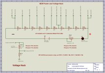
Simple wiring mistake by me inside MCM :roll:
Cells now balanicng before test drive tomorrow snow permitting.

Pack resting voltage 200V should be fun or blow up one of the two :shock:
 
Is this 200v resting pack level with the 40Ah thundersky cells?
 
No this is on my test car which is fitted with 50 x A123 20 ah pouch cells and 20 x 8ah Lifebatt 8ah cells in 2P10S config. So effective capacity is reduced slightly to 16ah. I may add another 10 x 8ah cells to make it a 3P10S config and get back my lost 4ah. They all fit in IPU compartment couple of pics to show current test layout.

POWERMODS 014.jpg

POWERMODS 015.jpg
 
Todays testing.

Saw 114A briefly at about 170V which was just over 19kw but it gave a P1440 error after a couple of seconds.
This is a generic IMA system problem. Interesting that is wasnt directly related to voltage or current sensors that we are spoofing.

I suspect this is linked to

1) A second current cross check perhaps in the phase sensors? Not sure if that's likely or not.

2) My BCM current hack pot is not man enough to deal with the BCM current sensor 5-20ma output so I need a 300R resistor capable of a couple of watts (same as stock parts).

When using 50A of assist in top gear it worked for a good 10 seconds before error occured. More gradual heating of my tiny pot?

With WOT error occurs in couple of seconds max.

I might also try setting the current limit back to stock and just using the voltage hack so the increased voltage gives us more power rather than the increased voltage & current.

180V at 100A is still 18kw :)

Cells are so cold <0C could be due to voltage sag under load being so high IMA thinks there is a problem somewhere like a bad connection causing voltage drop. Drop from resting V at present is around 30V at 100A, the higher the system voltage, the higher the percentage voltage drop becomes. :(

Anyway it hasnt blown up, just got a bit more fiddling to do. DC-DC converter seems happy.

Desperately need some warm weather but no nope of that for a few weeks.

Comments?
 
Back now from 50 mile trip. No errors now.

I disabled the current mod to see what happens and had no errors. Saw 15.7kw peak.

I think I was shooting for too high a current initially so will change the current reduction from 25% to (15% or 10%) this will bring it nearer 100A at it's peak. If there is a triple current check then keeping it at or just below 100A has a few advantages and might get round that.

I will add two more cell pairs to bring the voltage up a little further (62 cells). The sag is considerable and they hover around 196-197v when surface charge has gone. I think we can go a little bit higher. May need to adjust the voltage mod to increase the reduction slightly to say 18% to compensate for the slightly higher pack voltage.

I could go to 65 cells without much trouble. By limiting fully charged voltage to 3.55v per cell this reduces stress on cells and gives a better lifespan for a pack max V of 230V. Hmm!
 
I doubt the error code is related to the current. I bet the voltage is sagging below 3v cell with the cells freezing cold.
 
The IMA system errors are completely seperate to the cell BMS errors. They are sagging to below 3V but that doesnt matter.

Further testing reveal no problems after i removed the current mod. So i will adjust that for a 10-15% reduction instead of the 25% i went for before.
 
Temperature marginally higher today 1-2C and i'm off work now for a few days. :)
I went on a 20 mile trip no errors and consistently good power. Peak of 16.1kw but cells are still around freezing. So a bit more to come when they warm up. Sag to ~165V under 100A load at the moment which ties in with peak kw readings pretty well.

I am now settled on current reduction of 12% and voltage reduction of 16% for the time being. After some more testing with better weather in the spring I may up the voltage by a few more cells.

The Current hack is considerably simplified and now comprises three resistors!
Highest I saw today was 101A

The Voltage hack is similiar and comprises three resistors.
Cells are resting at around 197V so room for a little more voltage.
 

Attachments

  • VoltageHack271210.jpg
    VoltageHack271210.jpg
    71.6 KB · Views: 999
  • CurrentHack271210.jpg
    CurrentHack271210.jpg
    22.6 KB · Views: 999
I went for 17% current increase a few days ago seems fine. Peak power 17.7kw according to BCM gauge during a few test runs. I might try 20% over weekend. (I know 25% did not work from earlier testing)

I may then also tweak the Voltage reduction upto 18%-20% from my current 16%. The idea is to keep the detected voltage just above the BCM/MCM error or low battery point, and around 140-144V under load. That encourages the MCM to allow maximum current. I migh supply these voltage points from a fixed voltage soure say a couple of zeners to keep voltage at optimum at all time.

I'm going to do a spreadsheet to make the caluculations for the various current and voltage pot settings a bit easier. :)
 
Good report. Are you beginning to see that it would be possible to buy the necessary pieces from an Auto Salvage yard,and install them into a conversion-new vehicle build ?? The Computer part of the conversion, is what bothers me.

I would like to try this stuff in my Tadpole build. Just need to be sure I could get it to work, before I start buying the goodies. Great work. Thanks for posting the updates.
 
Finally got the modified insight on a rolling road and here are the power graphs ;) Very interesting.

Didn't blow up or melt down.

This was using 20% current hack and fixed 130v voltage hack with 50 x A123 20ah cells at 25C and 95% Soc

Peak current was about 116A at 155V = 17.98kw

http://www.solarvan.co.uk/mdm/RollingRoad240211_1.jpg
http://www.solarvan.co.uk/mdm/RollingRoad240211_2.jpg

The above files are about 1mb so you can zoom in.

http://www.youtube.com/watch?v=XApi5SVuv_k
http://www.youtube.com/watch?v=Hh8dtCzqd24

From the Insight Encyclopedia standard specs are below. Note different units on graph!

Output.................................5-Speed Manual.....................CVT Automatic
Horsepower @ RPM / with IMA:
(SAE net)).........................67 @ 5700 / 73 @ 5700.........65 @ 5700 / 71 @ 5700
Torque (lb-ft) / with IMA:.....66 @ 4800 / 91 @ 2000.........65 @ 4800 / 90 @ 2000

enperformance.jpg
 
Back
Top