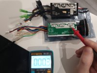
Well, first, as noted, just verify what's at the 3v3 pad, before you worry about anything else.
Other thoughts below:
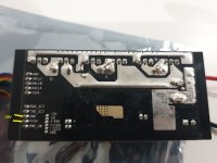
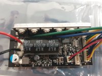
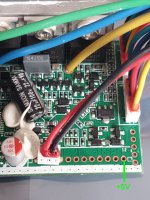
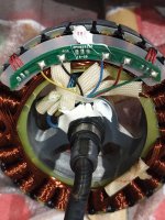
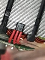
Oh no no, there is the mentioned 3 seperate phase wires and a 5 pin connector which goes to the motor and would be the halls thats the top left on the PCB which has the voltage label discrepancy, the bottom left 5 pin connector which goes to the lcd unit and theres a 2 pin connector for brake light, they cant be plugged wrong so theres no issue as it wouldnt work at all
Doesn't matter if they can be plugged in wrong or not.
The order of the wires can be different.
If they are different, it doesn't work the same, and you can have the problem you see.
If you don't want to check the wire order, that's ok, but if it's the problem and has to be changed to correct it, you won't be able to fix your scooter.
How can I find out if "pad x" on the controller goes to "motor blue wire"
By checking and writing down these:
What pad on the old board is connected to the *motor* blue phase wire?
What pad on the old board is connected to the *motor* green phase wire?
What pad on the old board is connected to the *motor* yellow phase wire?
What pad on the old board is connected to the *motor*'s first hall signal wire?
What pad on the old board is connected to the *motor*'s second hall signal wire?
What pad on the old board is connected to the *motor*'s third hall signal wire?
What pad on the old board is connected to the *motor* hall power wire?
What pad on the old board is connected to the *motor* hall ground wire?
What pad(s) on the old board are connected to the *motor* (other wires, if any)?
Then check and write down these:
What pad on the new board is connected to the *motor* blue phase wire?
What pad on the new board is connected to the *motor* green phase wire?
What pad on the new board is connected to the *motor* yellow phase wire?
What pad on the new board is connected to the *motor*'s first hall signal wire?
What pad on the new board is connected to the *motor*'s second hall signal wire?
What pad on the new board is connected to the *motor*'s third hall signal wire?
What pad on the new board is connected to the *motor* hall power wire?
What pad on the new board is connected to the *motor* hall ground wire?
What pad(s) on the new board are connected to the *motor* (other wires, if any)?
If they are all the same pads to the same things on the motor, then there's nothing to rewire.
If they are not the same then rewire the new controller to match.
To check them, if they are all visible individual wires, you can trace them by eye.
If they end inside a connector you cannot see which wires go to which pins, then you will need to use your multimeter with it's ohms or continuity function (see it's manual for how to use it for that) to find out which pin goes to which wire/pad.
they were just connected blue to blue wire, yellow to yellow, and green to green and thats how I plugged them to the new one, I would assume they wouldnt put mismatching colors
Color
Does
Not
Matter.
")
You cannot assume that colors will match.
Sometimes you get lucky; colors *might* match, but they don't have to. I recommend looking up the many posts and threads about finding the right phase / hall wiring combo (combination), to see how this works on various systems. Many times you will find phases wired with, oh, say Y-Y G-B B-G from controller to motor, and the halls in a different pattern, say, Y-B B-G G-Y, to make the motor run smoothly at the right speed at the lowest no-load current.
I've even seen controllers that have all the *same* color wire for everything--one I have has green wires for every single hall and phase wire, including ground and power.
There are even systems that use totally different wire colors on one side of a connector/cable--I have motors that use red, white, and black for phases, but the controllers don't, and the halls may be purple, green, orange, with grey and yellow as power and ground. Etc.
I didnt mean to short the two voltages supplies, but to connect the 5v unused pad to something (whatever is on that side I havent looked yet) which would make the 3v output as 5v instead like on old controller, I am thinking of it as a optional "switch" sort of if something like that is even possible
Unless you cut and change things on the board to modify what is wired to the 3v3 pad, you can't make it output anything different than whatever it is wired to output.
I don't recommend doing that, as you risk breaking other board functions, or destroying parts, unnecessarily.
There isn't a need to switch anything either. You just find what you need to supply, where to get it from, and wire it up. If this was something you intend to experiment with many different motors that have halls with different power supplies (I don't know of any) then there would be a reason for a switch....
Instead, *if* it does not output the same thing your old board did, move the wire from the motor that goes to that pad to a pad that *does* output the same thing your old board did. It's that simple.