Motor Controller with Customizable Electronics, easy DIY and repair OpenSource

Woly said:
badgineer said:
Hi.

Is anybody from the EU area interested in a group order? I'd be interested in participating (but not organizing :D)

Did you get a board? I'm curious how testing is going.
I will receive tomorrow or after, the components from Mouser. There was an issue, the mosfet drivers that I bought from Aliexpress, shipping were canceled and I were waiting 1 month for them. So now I am planning to buy them from LCSC components, but only after I assembly the parts that will arrive from Mouser and see If I need to buy anything more other than the mosfet drivers.

So to resume, I think I will take at least +1 month to get the board fully assembled. No big issue as I am busy with EasyDIY display for Bafang M500/M600 motors.
 
Hi Everybody.

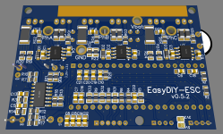
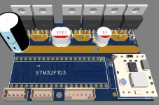
I just made a pull request for v0.5.2.
many minor improvements - but overall electrically almost identical to the v0.5. Software will need tiny changes though

Here's the "change log"

### Schematic
* changed voltage sense resistors to 10x lower value (basic jlcpcb resistors -> cheaper)
* removed pin 20 from GND (for blackpill compatibility)
* removed thermal reliefs
* replaced some parts with more cost-effective equivalents (basic parts jlcpcb)
* changed diodes to a bigger more rugged version (more inline with the philosophy of this controller)
* changed voltage sense divider so max read voltage is 100V (20s compatibility)
* added circuitry for a ntc temp sensor for mosfets.
* changed the electrolytic caps from the 12V and 5V rails to MLCC (still more capacitance than manufacturer recommends)
* swapped ntc pins: MOSFET Temp -> A0, and Motor Temp -> A1 (for compatibility with EBiCS v2)
* changed pinout of HALL JST connector - now you can use, additionally to a 6 pin connector for motors with temp NTC sensor, a 5pin connector on pins 1-5 and it will directly be compatible with the cable of a motor without temp sensor (M365 would be a popular example)
### PCB Design
* added 3 through hole pads for vbat, 12v, and gnd for easy connection with wires of any dc-dc module for more flexibility
* moved JST connectors away from bluepill for better fitting (increased board width by 1mm)
* removed soldermask from switch nodes, so conductivity can be improved (solder, etc)
* many minor layout changes

I think I am done with this version (0.5.*) - meaning other than fixes I will not change anything.

Hope to do some more substantial improvements though for v0.6 - but that's far in the uncertain future.

Here some pics :)
3D_SMD_Side.png
3D_TH_Side.png

Br,
 
afzal said:
Hi Badgineer < i am at a loss on how to address you properly :( >,

"Badgineer" is my best try at self-deprecating humor, so I don't mind if you call me that - or find something you like.
Actually if badgineer is too long/werid, just call me "Bad", sounds kinda cool :D

afzal said:
@badgineer, in the ST paper (5.2.1, p61) linked by stancecoke

It is noted that two current samples are not simultaneous but the start of the second current
sampling is delayed from the first current measurement by its global conversion time (Ts +
Tc); this introduces a conceptual error in the third current computation using the relation
given in Section 7.2: "Current sampling in three-shunt topology using one A/D converter",
because the two current samples are referred to two different time instants and this
equation is true if the three current values are referred at the same time instant. Anyway,
this error is negligible for a width range of motors.

The FOC systems I have worked with so far did simultaneous sampling, perhaps the easiest way would be to compare FOC performance w/ & w/o simultaneous current sampling on same platform.

That is sort of what I expected. That the error is negligible if samples are close enough together. I also remember vaguely to have seen ST uCs supported by ST for FOC which have only 1 ADC. So in the end it should be doable. (out of my reach but doable)

Thanks for your input, really appreciate it :)
Br,
 
Hi flute2k3

flute2k3@hotmail.com said:
this version is for prototype test only since I'm not very confident to design a full power board. it is intended for 2A max battery current only, my purpose is to test and learn all the versions, I will design a final version based on this test board. not sure if it is any help, if you need more detail please leave your e-mail, I can send you the original Gerber file.
T.jpg
B.jpg

I looked a bit at your board and there seems to be some room for improvement if I understand it correctly...
I suggest you take a look at v0.5.2 (or v0.5) - I invested quite some thought and time in them, and maybe you should "steal" some ideas at least, if not base your work directly on them. You know, open source :)
Also, I wrote all changes / improvements from v0.1 in a changelog. That might help.
But I think the most valuable thing you could take is the layout - most of my effort went into that. Not saying it's pro level, I'm an amateur, but I took all advice i could get (a lot from mxlemming, thanks!) and I expect the result to be decent :).

Br,
 
Here are the images of fully assembled last version (v0.5_2022-03-19). Well, is missing / yet to be assembled, the battery wires as also the BIG capacitor on the battery wires.

The board needs to be a slightly larger to have more room for the hall sensor connectors / red capacitors and that 3 big capacitors.

The board was not yet tested, I will test it probably on next days:


This thread is sooooooo 'friggin cool. It is absolutely awesome for someone who want to learn. The "EasyDIY ESC". You guys are great.

I just wanted to say that. I will resume lurking now.
 
badgineer said:
afzal said:
Hi Badgineer < i am at a loss on how to address you properly :( >,

"Badgineer" is my best try at self-deprecating humor, so I don't mind if you call me that - or find something you like.
Actually if badgineer is too long/werid, just call me "Bad", sounds kinda cool :D

afzal said:
@badgineer, in the ST paper (5.2.1, p61) linked by stancecoke

It is noted that two current samples are not simultaneous but the start of the second current
sampling is delayed from the first current measurement by its global conversion time (Ts +
Tc); this introduces a conceptual error in the third current computation using the relation
given in Section 7.2: "Current sampling in three-shunt topology using one A/D converter",
because the two current samples are referred to two different time instants and this
equation is true if the three current values are referred at the same time instant. Anyway,
this error is negligible for a width range of motors.

The FOC systems I have worked with so far did simultaneous sampling, perhaps the easiest way would be to compare FOC performance w/ & w/o simultaneous current sampling on same platform.

That is sort of what I expected. That the error is negligible if samples are close enough together. I also remember vaguely to have seen ST uCs supported by ST for FOC which have only 1 ADC. So in the end it should be doable. (out of my reach but doable)

Thanks for your input, really appreciate it :)
Br,

If this works well perhaps you can upgrade your name to goodgineer.

I'm going to get one of these and port my FOC code to the black pill as soon as casainho has spun a motor. Will be easy to see whether the whole lot works with the error... I bet you won't even notice.

My very rough mathematical assessment is:
20uH phase to phase motor (very low for ebike)
80V drive (20s with most of its charge)
ADC running 1MHz... 1us gap
That's a 4 amp difference with real worst case values. Realistically, the motor will be higher inductance, drive voltage lower and the black pill can be run at 2x that frequency... You also tend to sample on the phases with lower modulation so that chips away that error again.

The big question for me is really how well it runs things like HFI. Current offsets could be quite unfriendly to that, though at low speeds the errors decrease proportionally...

Really excited about this. As badgineer notes, I've been helping a bit with his questions on telegram but it's 99% his. I've had just enough involvement that I really want to get one to try.
 
mxlemming said:
If this works well perhaps you can upgrade your name to goodgineer.

Really excited about this. As badgineer notes, I've been helping a bit with his questions on telegram but it's 99% his. I've had just enough involvement that I really want to get one to try.
The name of the project is a clear statement of what it is, his identify.

Badgineer is doing an amazing work but there was a first board version done by Andrii. This is a project done in collaboration of several developers. The project is above the ego of a specific developer.

About the Blackpill, that would be great!!
 
Hi

casainho said:
[..] but there was a first board version done by Andrii. This is a project done in collaboration of several developers. The project is above the ego of a specific developer.

Yup! The concept, which I think is awesome, and the first iteration were done before I even knew about it :). So credit where credit due. I just took over implementation :)

DogDipstick said:
This thread is sooooooo 'friggin cool. It is absolutely awesome for someone who want to learn. The "EasyDIY ESC". You guys are great.
For learning - give the readme file a look. I tried to explain some of the design decisions there. Maybe you can find something interesting. Or something wrong! :D

If you find anything wrong or weird, please let us know/ask about it. Maybe I can explain it, or maybe I should fix it :)

Br,
 
casainho said:
mxlemming said:
If this works well perhaps you can upgrade your name to goodgineer.

Really excited about this. As badgineer notes, I've been helping a bit with his questions on telegram but it's 99% his. I've had just enough involvement that I really want to get one to try.
The name of the project is a clear statement of what it is, his identify.

Badgineer is doing an amazing work but there was a first board version done by Andrii. This is a project done in collaboration of several developers. The project is above the ego of a specific developer.

About the Blackpill, that would be great!!
Apologies to Andrii, who made the original schematic and first board. Hopefully he is able to return to the project soon.

We should recognize the individuals behind things and their efforts. The efforts are substantial.
 
mxlemming said:
We should recognize the individuals behind things and their efforts. The efforts are substantial.
Sure!! For instance on the firmware, the files can have the authors name at the top, with the license. And in the projects I already participated, the developers come and go. It is good their names and contributions are recorded. For instance, using Git is good on that since there is a track of user name and e-mail on the commits / pull requests.
 
badgineer said:
I looked a bit at your board and there seems to be some room for improvement if I understand it correctly...
I suggest you take a look at v0.5.2 (or v0.5) - I invested quite some thought and time in them, and maybe you should "steal" some ideas at least, if not base your work directly on them. You know, open source :)
Also, I wrote all changes / improvements from v0.1 in a changelog. That might help.
But I think the most valuable thing you could take is the layout - most of my effort went into that. Not saying it's pro level, I'm an amateur, but I took all advice i could get (a lot from mxlemming, thanks!) and I expect the result to be decent :).
No doubt at all! definitely I will make a normal rating board by absorb the good thing from your work. currently I'm busy with some other thing and also I'm trying to put more efforts to digest the codes.
 
flute2k3@hotmail.com said:
I temporarily give up on v2 and shift to v3, I follow the instruction here: https://github.com/OpenSourceEBike/TSDZ2_wireless/blob/master/EBike_wireless_remote/documentation/development-flash_and_debug_firmware.md
however since I use win10, very difficult to make it work, missing path/file here and there. I then shift to "stancecoke" version - v0.5 branch of v3, connect a hall throttle to pin A1, of cos +5V and GND as well, but it does not work at all when energized, not sure what is the issue. in order to walk around my DC/DC with no EN pin, I connect PC14 directly with +3.3V, so it shall be no problem and it does work well on v2.

@stancecoke, any hints for your v3 0.5b?
I find the issue for V3-0.5 here, same for V3
1.JPG
2.JPG
3.JPG
the ADCTHROTTLE starts very later in while loop, so the system halts and will never go to throttle.
 

Attachments

  • 4.JPG
    4.JPG
    23.2 KB · Views: 955
flute2k3@hotmail.com said:
I find the issue for V3
Hm, why should the UART DMA initialization fail? :shock:
The throttle signal has to be connected to PA7 on v05 and this line has to be uncomment in the config.h
https://github.com/Koxx3/SmartESC_STM32_v3/blob/4bd351263779947dabdfd69c4bce9a643eabba9e/Core/Inc/config.h#L22

regards
stancecoke
 
stancecoke said:
Can you provide a detailed comparison? How much is the difference at which speed? We did a lot of tests with V2 and V3 on the telegram chatgroup, be we never found noteworthy differences.

regards
stancecoke

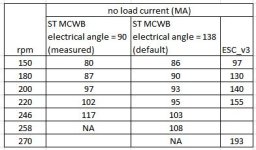
I'm able to provide a comparison now, the test is based on 18V voltage for a small motor with no load, may not reflect the loaded condition:
Capture.JPG

I get the value by directly setting the iq_target value, the ESC_v3 (SmartESC_STM32_v3 firmware) can reach highest rpm compared with ST MCWB (codes generated by ST Motor Control WorkBench), which on the other hand means the id_target is not tracked very well.

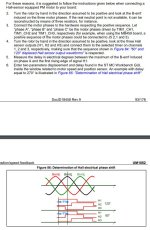
when shifting the rotor electrical angle, it is interesting to see a slight difference on efficiency, 90 degree is the real degree I measured, while the 138 is ST MCWB default value. the real angle shows good tracking at low speed, but getting worse at high speed, which could imply the calculation burden increase with the speed, make the tracking delay/worse.
 
flute2k3@hotmail.com said:
when shifting the rotor electrical angle

Thank you for the feedback, but I can't follow your experiments :confused:
The rotor angle is detected by the autodetect routine in v3. You have to run it once, otherwise the controller won't know the correct positions of the hall sensors.

I don't know, how the MC WB manages the hall sensor position, but it seems not plausible, that the efficiency in idle run doesn't change dramatically, if you misstune the angle by nearly 50 deg.
Easiest way is to look at ud, to see, if the rotor angle is proper. The more you misstune the rotorangle, the bigger the amount of ud will be, if you control id to zero...

index.php


regards
stancecoke
 
stancecoke said:
flute2k3@hotmail.com said:
when shifting the rotor electrical angle

Thank you for the feedback, but I can't follow your experiments :confused:
The rotor angle is detected by the autodetect routine in v3. You have to run it once, otherwise the controller won't know the correct positions of the hall sensors.

I don't know, how the MC WB manages the hall sensor position, but it seems not plausible, that the efficiency in idle run doesn't change dramatically, if you misstune the angle by nearly 50 deg.
Easiest way is to look at ud, to see, if the rotor angle is proper. The more you misstune the rotorangle, the bigger the amount of ud will be, if you control id to zero...

index.php


regards
stancecoke

this is the big advantage of your firmware with autodetect, MCWB can not do that, you have to manually set a value, I follow this direction to get the real value
angle.JPG

I'm trying to lean and figure out a way to "autodetect" the rotor angle, to make it more flexible to any kind of motors.
 
flute2k3@hotmail.com said:
stancecoke said:
flute2k3@hotmail.com said:
when shifting the rotor electrical angle

Thank you for the feedback, but I can't follow your experiments :confused:
The rotor angle is detected by the autodetect routine in v3. You have to run it once, otherwise the controller won't know the correct positions of the hall sensors.

I don't know, how the MC WB manages the hall sensor position, but it seems not plausible, that the efficiency in idle run doesn't change dramatically, if you misstune the angle by nearly 50 deg.
Easiest way is to look at ud, to see, if the rotor angle is proper. The more you misstune the rotorangle, the bigger the amount of ud will be, if you control id to zero...

index.php


regards
stancecoke

this is the big advantage of your firmware with autodetect, MCWB can not do that, you have to manually set a value, I follow this direction to get the real value
angle.JPG

I'm trying to lean and figure out a way to "autodetect" the rotor angle, to make it more flexible to any kind of motors.

The best way i found to do this is to run it very slowly in open loop with a high d axis current, integrate the angle and count the number of steps per every hall state.
Then after a full revolution divide the integral by the count for each hall state.
That gives you the centre angle of each hall sensor. You have to do some messing around for the hall state that overflows 360 degrees.

E.g.
Set id is 20A
For 360 degrees, each pwm period increment the angle 0.01 degrees
Make a table of 6 elements, one for each hall state
Each pwm period, add the current angle to the angle integral in the table and add 1 to the count.
After 360 degrees, your sum of counts will be 36000 with roughly 6000 counts for each. Your angle integrals will be approximately 60x6000, 120x6000... Etc.

If you do the division in the above table... You have a very accurate estimate of the sensors.
 
mxlemming said:
The best way i found to do this is to run it very slowly in open loop with a high d axis current, integrate the angle and count the number of steps per every hall state.
Then after a full revolution divide the integral by the count for each hall state.
That gives you the centre angle of each hall sensor. You have to do some messing around for the hall state that overflows 360 degrees.

E.g.
Set id is 20A
For 360 degrees, each pwm period increment the angle 0.01 degrees
Make a table of 6 elements, one for each hall state
Each pwm period, add the current angle to the angle integral in the table and add 1 to the count.
After 360 degrees, your sum of counts will be 36000 with roughly 6000 counts for each. Your angle integrals will be approximately 60x6000, 120x6000... Etc.

If you do the division in the above table... You have a very accurate estimate of the sensors.

Exactly! autodetect (https://github.com/Koxx3/SmartESC_STM32_v3/blob/v0.5/Core/Src/main.c#L254) does the same as you said, more specifically 1 degree (11930465/0xFFFFFFFF)... what is the purpose to set a high id here? is that much id force the locking/blocking of rotor movement step by step/degree by degree?

another confusion is, though it specifies the Rs - stator resistance and Ls stator inductance in MCWB, I do not see the codes use it. what is the purpose to measure it?
 
flute2k3@hotmail.com said:
what is the purpose to set a high id here?
The idea is to make the rotor with its permanent magnets aligne itself automatically to the magnetic field caused by the current through the stator coils.

flute2k3@hotmail.com said:
I do not see the codes use it. what is the purpose to measure it?
This motor constants are only needed for sensorless run. The observer needs this data for the virtual motor model.

regards
stancecoke
 
flute2k3@hotmail.com said:
mxlemming said:
The best way i found to do this is to run it very slowly in open loop with a high d axis current, integrate the angle and count the number of steps per every hall state.
Then after a full revolution divide the integral by the count for each hall state.
That gives you the centre angle of each hall sensor. You have to do some messing around for the hall state that overflows 360 degrees.

E.g.
Set id is 20A
For 360 degrees, each pwm period increment the angle 0.01 degrees
Make a table of 6 elements, one for each hall state
Each pwm period, add the current angle to the angle integral in the table and add 1 to the count.
After 360 degrees, your sum of counts will be 36000 with roughly 6000 counts for each. Your angle integrals will be approximately 60x6000, 120x6000... Etc.

If you do the division in the above table... You have a very accurate estimate of the sensors.

Exactly! autodetect (https://github.com/Koxx3/SmartESC_STM32_v3/blob/v0.5/Core/Src/main.c#L254) does the same as you said, more specifically 1 degree (11930465/0xFFFFFFFF)... what is the purpose to set a high id here? is that much id force the locking/blocking of rotor movement step by step/degree by degree?

another confusion is, though it specifies the Rs - stator resistance and Ls stator inductance in MCWB, I do not see the codes use it. what is the purpose to measure it?

Stator resistance and inductance should be used to tune the PI loop for the current controller. Proportional term should be your control bandwidth*Ls and the Integral term should be P term*Rs/Ls
Typical control bandwidth should be about 1000rads-1 for an ebike. Servo control should be higher, big motors strapped to pumps etc lower.
https://github.com/davidmolony/MESC_Firmware/blob/2dd04d17b6f5d73e18a7701c0fc0113569c5930b/MESC_Common/Src/MESCfoc.c#L1270
See this where I've cunningly set the bandwidth at 2500rads-1 and in the comments said 10000.

Note that I'm using a series pi controller. If you use parallel you'll need to adjust the math accordingly.

The smart ESC routine is not the same as the one i described, it will be much less accurate since it relies on single point detection.
 
mxlemming said:
Stator resistance and inductance should be used to tune the PI loop for the current controller
I always tune the PI parameters by trial and error, not by the mathematical/physical theory :D

mxlemming said:
it will be much less accurate since it relies on single point detection
Yes that's right, the autodetct routine could be improved a lot, but the accuracy is sufficient at the moment, so I'm not motivated to that :wink:

mxlemming said:
That gives you the centre angle of each hall sensor.
So you have to add/substract 30 deg in the hallsensor interrupt to get the real rotor position, depending on the rotor rotation direction ?!

regards
stancecoke
 
stancecoke said:
mxlemming said:
Stator resistance and inductance should be used to tune the PI loop for the current controller
I always tune the PI parameters by trial and error, not by the mathematical/physical theory :D
good to know, it makes sense. my purpose is to make a generic firmware for various motors, so I like mxlemming's way, but for M365 motor only, stancecoke's fine tune shall get best working point.

stancecoke said:
mxlemming said:
it will be much less accurate since it relies on single point detection
Yes that's right, the autodetct routine could be improved a lot, but the accuracy is sufficient at the moment, so I'm not motivated to that :wink:
I'm not good at coding/reading the codes, just checked again, yes stancecoke's routine counts the first hall status changing position (entering the hall sensor) and ignore all the next until the status change again (leaving), which is not accurate. the accurate position shall be the center of between the "entering" and "leaving" of the hall sensor. notice that for my comparison test, 48 degree rotor angle change results in different performance, could imagine accurate measurement of angle, plus a calculation consumption delay (fine tune) shall achieve better performance, especially for generic motor application.

stancecoke said:
flute2k3@hotmail.com said:
what is the purpose to set a high id here?
The idea is to make the rotor with its permanent magnets aligne itself automatically to the magnetic field caused by the current through the stator coils.
you are correct, big id and small iq compounds a small torque, prevent an excessive turn more than desired angle/step due to inertia.
 
stancecoke said:
mxlemming said:
Stator resistance and inductance should be used to tune the PI loop for the current controller
I always tune the PI parameters by trial and error, not by the mathematical/physical theory :D

mxlemming said:
it will be much less accurate since it relies on single point detection
Yes that's right, the autodetct routine could be improved a lot, but the accuracy is sufficient at the moment, so I'm not motivated to that :wink:

mxlemming said:
That gives you the centre angle of each hall sensor.
So you have to add/substract 30 deg in the hallsensor interrupt to get the real rotor position, depending on the rotor rotation direction ?!

regards
stancecoke
The mathematical way is easier once you've had to do it more than once.

Indeed, if you have a pll, you can get away with mediocre accuracy.

You don't add/subtract 30 degrees to get the end points, you add/subtract half the width of that hall sensors angle (half the "count" I described above). It will be close to 30 degrees but my experiments have found motors where the hall sensor states occupy at much as 90 degrees and as little as 45...
 
flute2k3@hotmail.com said:
I'm not good at coding/reading the codes, just checked again, yes stancecoke's routine counts the first hall status changing position (entering the hall sensor) and ignore all the next until the status change again (leaving), which is not accurate. the accurate position shall be the center of between the "entering" and "leaving" of the hall sensor. notice that for my comparison test, 48 degree rotor angle change results in different performance, could imagine accurate measurement of angle, plus a calculation consumption delay (fine tune) shall achieve better performance, especially for generic motor application.

48 degrees is an enormous error. That's basically eliminating the difference between d and q axis. That's not conceivable in normal use unless you literally don't try. Any detection routine can easily get 5 degrees.
 
Back
Top