Motor Current Limiting: More Power and Less Heat!!!

safe said:
eP said:
Before you start the think which way is easiest, the better is start to calculate what we can gain after conversion and what we will lost.

:arrow: We're moving on to the circuit design now.

Suffice to say that you now know that you have an "option". If you decide on using gears on your bike then you have the option of trying this controller design to optimize the benefits of gears.

Option for which motor ?
If you want upgraidnig this way very efficient motor yours gain will be relatively small and torque sacirfice relatively high.
Think about for 95-99% efficient motor for example.

If you want that circuit for relatively inefficient motor the gain will be higher but torque sacrifice still relatively high. So the better option at this case will be changeing the motor for more efficient one without any sacrifice.

So since now i will be completely silence.
Good luck.
 
TylerDurden said:
That application of motor-side current limiting is simply another way of reducing power to the motor. Lower power at the motor may reduce the potential for overheating, but the resulting loss of torque may significantly limit the usefulness of the method:

Torque will generate heat. A specific amount of torque is needed to accellerate. The resulting heat will need to be dissipated.

How much torque will be generated?
What amount of heat will be generated?
Can it be dissipated?
How many gears will it require?
How long will it take?

Fechter can make the circuit, there is little doubt about that.

Thanks Tyler
That is what i want to ask (but i have enough asking for now :wink: - i'm a little bit tired).
 
I like the design, but are you sure about using a relay instead of an amplifier or a varoistor?

The problem I see is the nature of a relay. They are either off or on. that can cause 2 problems here.

When the relay is tripped, the throttle shuts off as expected, and the motor amps fall off, the sensor sees the lower amps, and reactivates the throttle. And here's were thr problems start.

If your controller is like the crystalyte, they have a fault detection for the throttle. if you unplug it with the system armed, then plug it back in, the system won't work. the controller locks out the throttle untill the system is powered down and up again. On my controller, I usualy have to hit the big ged button 2 or 3 times after it's powered back up to get it to reset.


The second problem is the feed back loop. on most controllers, there is a delay between throttle going to full and the output on the motor putting out full power. even if there isn't a "soft on" feature built into the FETs, there is still a controller delay. having the output effect the input with a delay will cause a feedback loop on your throttle. That has the potential to cause some huge power and voltage spikes through the FETs and the capacitors. A controller is just an amplifier, Amplifiers hate feedback.


If you used some kind of Varistor, or amp design to lower the throttle level without killing it completely, you could overcome both problems.
 
Using the Allegro hall effect current sensor, the design of a current limiter gets much easier. A single op-amp a few other parts will do it. An op amp is probably cheaper than a ss relay anyway.

With the hall current sensor, you can mount the current sensing part anywhere in the circuit, since it's isolated. Motor or battery current would be equally easy. With the right filtering, you could also measure motor current on a brushless motor.

Basically, the current sensor outputs a voltage porportional to current. This signal would go to one input of a comparator. A potentiometer (the current limit control) would feed a voltage to the other input of the comparator. Whenever the current signal gets above the set point, the amp pulls the throttle signal down. Since everything is analog, the feedback loop will be stable as long as the filtering is adequate.

I'll draw one up when I get a chance. I want to build one also, since my first prototype has many bad features, but did work well enough to demonstrate the principle.

Plan "B" is to wait until Justin comes out with the new version of the DrainBrain, which will have this feature integrated into the design (along with many other cool features).
 
Drunkskunk said:
I like the design, but are you sure about using a relay instead of an amplifier or a varoistor?

The problem I see is the nature of a relay. They are either off or on. that can cause 2 problems here.

...

If you used some kind of Varistor, or amp design to lower the throttle level without killing it completely, you could overcome both problems.

Well I'm not certain about the circuit at all that's why this thread was created to extend the "Boost Control" concept (which is not bound to either the Battery side or the Motor side current) and move towards a focus on questions about the "Motor Current Limiting" circuit alone.

I agree that some sort of variable "voltage lowering" of the throttle is a good idea. The idea that Fechter has presented uses a lot of pots and it just seems like you have too many points of potential failure and error. Would I have to calibrate the pots before each ride? That's just too much effort.

Analog is tricky... a digital "on" or "off" of the throttle is easier to deal with in that the trigger is very clear.

I also like the fact that the components are "off the shelf" and would be of known parameters.

:arrow: This idea is definitely simple to do...

Fechter said that most controllers have "buffered" throttle ramping built in, so it might all be okay... OR... it might burn up a controller... :shock:
 
fechter said:
Using the Allegro hall effect current sensor, the design of a current limiter gets much easier. A single op-amp a few other parts will do it. An op amp is probably cheaper than a ss relay anyway.

With the hall current sensor, you can mount the current sensing part anywhere in the circuit, since it's isolated. Motor or battery current would be equally easy. With the right filtering, you could also measure motor current on a brushless motor.

Basically, the current sensor outputs a voltage porportional to current. This signal would go to one input of a comparator. A potentiometer (the current limit control) would feed a voltage to the other input of the comparator. Whenever the current signal gets above the set point, the amp pulls the throttle signal down. Since everything is analog, the feedback loop will be stable as long as the filtering is adequate.

I think your Opt amp would be even more stable than a varistor. What about if he skiped the hall sensor, and sampled the motor amps from the shunt inside the controler?
 
fechter said:
Plan "B" is to wait until Justin comes out with the new version of the DrainBrain, which will have this feature integrated into the design (along with many other cool features).

:arrow: Really?

So would this be flexible enough to use on the motor side?

Would that screw up all the other measurements?

(I would think that this would NOT screw things up because the case of current being linear is just a "special case" of current anyway... current would be current no matter what shape it's curve is...)
 
Drunkskunk said:
What about if he skiped the hall sensor, and sampled the motor amps from the shunt inside the controler?

Then you have to break into the controller... I'm using a Chinese brand so I can't really do that... (don't want to do that)
 
safe said:
Then you have to break into the controller... I'm using a Chinese brand so I can't really do that...

Not too difficult.

img_2939sm_128.jpg
 
fechter said:
Using the Allegro hall effect current sensor, the design of a current limiter gets much easier. A single op-amp a few other parts will do it. An op amp is probably cheaper than a ss relay anyway.

Don't obsess on the price. If a SSR can be bought for $5 and an alternative can be bought for 50 cents but it means I have to figure out more stuff I'll pay the extra $4.50 and "splurge" on luxury.

Price should not be the primary consideration... below $20 anyway...
 
TylerDurden said:
Not too difficult.

:( That's exactly the kind of "hacking around" inside a controller that I want to avoid. I know it's a "short cut" to an answer, but I'd prefer to keep the controller a "virgin" and "unmodified" and simply add an extra circuit.

:idea: The idea is to create a GENERIC solution to the problem... no "custom" conversion ideas in my own personal development process are going to be allowed. (you are free to enjoy your own process)

:arrow: If it were possible to create a standalone product it could be something sold over the internet... another source of $$$ for a business... (sounds like the DrainBrain might beat everyone to it though)
 
Safe:

When Justin is back from the Maker's Fair, I'll ask him how easy motor side current limiting would be to implement. The software has adjustable feedback parameters to eliminate overshoot and give smooth limiting, and sounds exactly like what you're looking for.
 
Lowell said:
When Justin is back from the Maker's Fair, I'll ask him how easy motor side current limiting would be to implement. The software has adjustable feedback parameters to eliminate overshoot and give smooth limiting, and sounds exactly like what you're looking for.

That would be great. What a big savings of effort that would be. Thanks. 8)
 
Efficiency vs Speed for the 8-Speed Motor Current Limited Bike

Finally got around to plotting the actual Speed/Efficiency going through the gears of an 8-Speed bike. The results look good and basically show that (like with all electric motors) the low speeds are the worst.

The data points represent the 8 gears.

Here's the chart... given that this motor is normally only about 78% efficient at it's best (it's a Unite motor) if it's possible to run it near the 74% zone all the time I would be doing pretty good.


Nearly 74% average out of 78% isn't all that bad!

eP your observation that first gear would show poor results was accurate... but the overall average is pretty good and the standard controller wouldn't be able to do much better even in first gear.
 

Attachments

  • efficiency vs speed (Motor Current Limited).gif
    efficiency vs speed (Motor Current Limited).gif
    15 KB · Views: 2,190
safe said:
Nearly 74% average out of 78% isn't all that bad!

eP your observation that first gear would show poor results was accurate... but the overall average is pretty good and the standard controller wouldn't be able to do much better even in first gear.

So tell us what is the nominal Power_out of that motor, and how much is efficient at 0.2 HP light load ?
I'm afraid it is big P_out motor and its efficiency at light load is pretty low.
But maybe i'm wrong ?

ps.
Thanks for the patience.
 
eP said:
So tell us what is the nominal Power_out of that motor, and how much is efficient at 0.2 HP light load ?
I'm afraid it is big P_out motor and its efficiency at light load is pretty low.
But maybe i'm wrong ?

Here's the idea... take this motor:

106155.gif


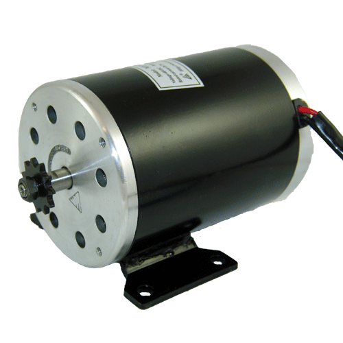
MY1020Z3 36 Volt, 750 Watt, 2800 RPM, 27.4 Amp

...and overvolt it to 48 volts. Then start to play around with the controller logic as I've done over the course of this thread.

You can recreate everything I've done starting from scratch if you desire... :wink:

I'll give you a couple of "hints". First you need to recreate the actual motor and not the chart posted because that's for the 24 volt version. Then you need to create a spreadsheet that before the controller gets involved produces a 78% efficiency rating at peak and also be sure that your no load and rated power figures all agree with the ones they have posted for 36 volts. You then overvolt that motor to 48 volts which doesn't change the key parameters like the motors resistance, but does increase the no load speed in direct proportion to the voltage increase. You then apply all the "weirdness" that "current multiplication" introduces to the standard controller and you then have to compare that to the "Motor Current Limited" controller concept. After all that you finally get to at a point where you can actually produce an intelligent observation based on real data that you have a mastery over.

However... eP... you have done a very good job of "guessing" at what is going on so your mathematical intuition is good... 8)


200582153958599.jpg


20058215408824.jpg
 
eP...

Just to make sure you have the "basics" down...

All electric motors have two basic areas of energy loss:

:arrow: 1. Back EMF

:arrow: 2. Resistance based Losses

When it comes to Back EMF (Electro Magnetic Field) this is the "push back" that those permanent magnets produce. The faster the motor spins the more the "push back" increases. At some point the energy going into the motor can't overcome the EMF based resistance and that's the top speed of the motor.

The Resistance losses are due to the fact that the wires that carry the electricity don't have perfect conductivity. You get two negatives with resistance... not only do you lose energy, but that energy turns into heat which then can build up over time and destroy your motor.

Back EMF rises in direct proportion to rpms.

Resistance losses are based on CURRENT so they actually can be rather variable depending on the way you set up your controller.

:arrow: This is where the "magic" comes in...

Power and Torque and Gears are all related in weird kinds of ways. Lowering the gears increases the rear wheel torque. Power is a combined value of instantantious torque of the motor and rpm. Back EMF tends to want to make you avoid high rpms (because high rpms means more "push back") but power is generated when you multiply instantanious torque times rpm.

So "everything is related" somehow...

Where the "Motor Current Limited" controller scheme finds it's benefits is when you have the luxury of gears and can afford to "phase out" unwanted low rpm/high current situations in favor of the higher rpm/higher power situations.

I'm kind of rambling here, but the point is that you have this "toolbox" of relationships that you can "tweek" in different ways depending on your intended usage. If you are focused on "peak power" and can sacrifice your low end you can use the "Motor Current Limited" technique. Otherwise, if you want a strong low end and are willing to forsake some top end power (for the sake of heat reduction) you go with the standard "Battery Current Limited" controller.
 
safe said:
eP...

Just to make sure you have the "basics" down...

All electric motors have two basic areas of energy loss:

:arrow: 1. Back EMF

:arrow: 2. Resistance based Losses
...
Back EMF rises in direct proportion to rpms.

Resistance losses are based on CURRENT so they actually can be rather variable depending on the way you set up your controller.

You forgot the stator loss or Fe loss if you like.

The stator loss rises faster than in direct proportion to rpms, and it is also depend on the current.
The thinner the stator sheets - the lower is stator loss. The same kind of loss you get at AC transformers. But transformers operating at relatively fow frequency 50-60Hz (depending on the system standard).
For the multi pole high rpms motors operating frequency are much higher (especially for high speed RC motors) so the stator loss could be a big issue.
The same loss you get for the inductor core materials. It is rising much faster then proportionally to frequency.
 
As with the MY1018, it would appear the MY1020 is a motor who's performance can only be guessed due to intellectually dishonest specs... Shame on you, Unite Motor.
 
Drag Race - Motor vs Battery Current Limiting

:arrow: Okay, I finally figured out how to calculate dynamic acceleration with my otherwise static based spreadsheet. The results are pretty much as expected, the "Battery Current Limited" bike with it's stronger low end torque gets a jump off the line and at 10 mph is a full 0.74 seconds ahead of the "Motor Current Limited" bike. After 10 mph things start to even out a little and by the time you get to the top speed the gap between the bikes is narrowed to 0.62 seconds at which point both bikes will shift gears. From then on EVERY gear will be faster for the "Motor Current Limited" bike because it has more top end.

So it's pretty much as expected... :roll:

:arrow: Top speed on the "Battery Current Limited" bike is 46.7 mph.
:arrow: Top speed on the "Motor Current Limited" bike is 50.0 mph.

So once you get rolling the "Motor Current Limited" bike is faster... but from 0-10 mph it's slower... so it's definitely a tradeoff... (if you could "slip the clutch" like the racebikes you could nail the throttle wide open and feather your way up to speed... but clutches are a definite "no-no" in Missouri, they are explicitly banned)
 

Attachments

  • 0 - 20 mph drag race.gif
    0 - 20 mph drag race.gif
    8.2 KB · Views: 2,302
Now what happens if you give the motor current limited bike a lower first gear? I'm sure you could get the difference down to zero and still have the same top speed.
 
Lowell said:
Now what happens if you give the motor current limited bike a lower first gear? I'm sure you could get the difference down to zero and still have the same top speed.

I was just thinking that... 8)

Yeah, you could play around with the gear spacing a little and after a while dial it in so that the disadvantage is less. Even adding an extra gear would help, though there comes a point where too many gears wastes time as well...
 
Well then I guess a push button to switch between battery and motor current would be an easy way to get those fast drag race starts. Wire in a temperature sensitive cutout, and it would be idiot proof.
 
Lowell said:
Well then I guess a push button to switch between battery and motor current would be an easy way to get those fast drag race starts. Wire in a temperature sensitive cutout, and it would be idiot proof.

You could use two Hall Effect Sensors, one on the Motor Side and the other on the Battery side. Off the line you use Battery side and then switch a switch and go Motor Side.

The one time heat would be okay since the motor starts out cold...

One might even run "unlimited" off the line. Just temporarily disengage the current limit and allow the current to jump up as high as you can allow without it blowing up...

How about a blast of icy cold inert gas inserted directly into the motor just for the start. Get triple the power for a short time and then settle back down to normal afterwards...
 
safe said:
Lowell said:
Well then I guess a push button to switch between battery and motor current would be an easy way to get those fast drag race starts. Wire in a temperature sensitive cutout, and it would be idiot proof.

You could use two Hall Effect Sensors, one on the Motor Side and the other on the Battery side. Off the line you use Battery side and then switch a switch and go Motor Side.

The one time heat would be okay since the motor starts out cold...

One might even run "unlimited" off the line. Just temporarily disengage the current limit and allow the current to jump up as high as you can allow without it blowing up...

Now you're talking!

The only current limit I want is higher one... :D

I was just setting up a nitrous intercooler sprayer on a customers car... how about a shot of cryogenic cooling along with unlimited motor amps? :twisted:
 
Back
Top