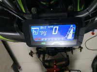
Drupa said:
I disconnected the motor hall plug & measured the voltage on the controller side, results are as follows:
Black & red = 5.4v
Black to each one of the 3 sensors input (Yellow, Green, Blue) = 3.3v
That is unusually low; 5v is typical for the signal pullups, sometimes 12v or even more, depending on the system. I've never had a controller that only used 3.3v, but that's apparently how what you have is designed.
Whether it is the cause of the problem, you would have to test the system identically with the old motor and the new one first. If identical tests (same phase currents, same motor speeds, etc) work normally on both motors, then you would test with them both at higher and higher phase currents and speeds until you run into problems (which may well happen at different points on each motor). When you begin to have problems you can use an oscilloscope to then compare between the working and non working states, to see what kind of signal shape and noise you get at the failure points.
Knowing that, you could then figure out what causes it, and come up with something to help eliminate the noise if tha'ts cuasing it. Alternately you could just try some of the standard fixes, like capacitors on teh signal and power lines (from the signal to ground at the controller,, and the power to ground at the motor itself,
Reminder:
I made the voltage measurements on my no issues motor & got also 3.29v on Halls without any errors.
But you said your other motor isn't as fast as this one, nor is it being run at as high a power level. Thus electrical noise on the signal lines is less, and has less chance of affecting the controller's ability to read the signals, with the smaller/slower motor that works, vs the faster/bigger one that doesnt'.
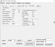
What does it mean if the pull up is 3.3v?
It means the same thing I already said--the lower the voltage, the less difference between "off" and "on", and so the greater the chance of electrical noise in the system (of which there is a lot because it is a motor with constantly changing currents and switching voltages/currents) causing a problem.
There is the possibilty that the halls themselves in the motor that doesnt' work are simply not able to switch fast enough, or cleanly enough, so once the motor spins fast enough, the hall signal is simply not clean enough for the controller to "understand". You'd need an oscilloscope to see this. If this is the case, replacing the halls with ones better able to switch quickly, and ones that sink more current when "on" (which makes a more stable "zero"), might fix it.