Motor Hall Fault

Hi Drupa,
Following along with interest...

In your previous post with the programmable screen shot pictures. You have two with the Page 1 settings, and none of the Page 3 settings. Could you post page 3?

And have you tried both outputs for the speedo? What display do you have?


Regards,
T.C.
 
TommyCat said:
Hi Drupa,
Following along with interest...

In your previous post with the programmable screen shot pictures. You have two with the Page 1 settings, and none of the Page 3 settings. Could you post page 3?

And have you tried both outputs for the speedo? What display do you have?


Regards,
T.C.
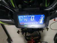
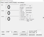
The speedo is OEM on the Quad using One-Lin output and woking fine, only when the RPM goes up bohe the RPM in the Display Tab and the Speed in my gage go crazy so it mean the Hall output really is loosing it


Attachments

  • 1609085356901.jpg
    1609085356901.jpg
    202.2 KB · Views: 1,709
  • SW Page 3.PNG
    SW Page 3.PNG
    11.9 KB · Views: 1,709
  • Display Tab.PNG
    Display Tab.PNG
    12.1 KB · Views: 1,709
larsb said:
Time to change that five :wink:
I also wonder if your hall connection and setting is ok. Only way to know is to do the trials.

The 5 pole is from old picture I took.
As i mentioned I rolled back to my Original black motor until I will get the hole sensors I ordered.

Update from toady:
I try to run the new 2000w motor on a bench test with my EM-50s (the OEM controller of my Quad) & suprsinglly I get constant Hall sensor fault!
I dont know if its because the hall sensor are damage becuase I still get on/off signal from each While i rotate the motor by hand or if it stuck on that error because of other missing parameter cause its the first time I try to run the controller outside of my Quad wiring Loom
Also worth the remind you all that while the 2000w motor was connected to the EM-150 I got the Motor Hall fault not Hall Fault

Side Note:
If someone can explain the function of the 'Flux Weakening' percentage which was by default on 60%.
When I firs try to over ride the restriction in my controller I messed a lot with all parameters especially Flux weakening upto 4000 value & while I got High RPM & 80Kmh on my speedo, on the road the accelration was poor & never reached the 80kmh that I got while the wheels are in the air, but when I changed the 'Flux Weakening' percentage from 60% to 20% the story totally changed, the accelaration of the inrunner was amazing and it reached close to the top speed with wheels in the air very fast
How exactlly is this value working? why is low value make the motor respond so much stronger?

Thanks
 
Drupa said:
larsb said:
Time to change that five :wink:
I also wonder if your hall connection and setting is ok. Only way to know is to do the trials.

The 5 pole is from old picture I took.
As i mentioned I rolled back to my Original black motor until I will get the hole sensors I ordered.

Update from toady:
I try to run the new 2000w motor on a bench test with my EM-50s (the OEM controller of my Quad) & suprsinglly I get constant Hall sensor fault!
I dont know if its because the hall sensor are damage becuase I still get on/off signal from each While i rotate the motor by hand or if it stuck on that error because of other missing parameter cause its the first time I try to run the controller outside of my Quad wiring Loom
Also worth the remind you all that while the 2000w motor was connected to the EM-150 I got the Motor Hall fault not Hall Fault

Side Note:
If someone can explain the function of the 'Flux Weakening' percentage which was by default on 60%.
When I firs try to over ride the restriction in my controller I messed a lot with all parameters especially Flux weakening upto 4000 value & while I got High RPM & 80Kmh on my speedo, on the road the accelration was poor & never reached the 80kmh that I got while the wheels are in the air, but when I changed the 'Flux Weakening' percentage from 60% to 20% the story totally changed, the accelaration of the inrunner was amazing and it reached close to the top speed with wheels in the air very fast
How exactlly is this value working? why is low value make the motor respond so much stronger?

Thanks
Correction - the value is Flux Weakening Compensation and its in percentage
 
Drupa said:
*** Yes, I measured the input 5v on the PCB & measured 3.29v on the PCB rom the PCB sensor output, I did it to eliminate the wires as the cause for the voltage drop, so it means that the Hall some how output almost 2v less than what recevied in it Input ***
This is important to how the system works, and a possible reason for the problems you have.

The motor halls don't output any voltage.

The halls only ground their output when they are "on", so you get near zero volts when a magnet is passing them.

When they are off (no magnet) the output "floats", with no valid voltage, so the controller has pullup resistors from each signal line to a voltage inside the controller. Usually this is the same 5v the halls are powered from, but sometimes it is 12v, or some other voltage.

To find out what voltage the controller actually has on the pullups, you would disconnect the motor from the controller, and measure the voltage on the controller's hall connector (not the motor). If the voltage is not about 5v (or about 12v), then there may be something wrong with the controller, even if it appeared to work with a different motor.

As noted before, generally the lower the pullup voltage, the harder it is for the controller to reliably distinguish between on and off, especially at higher motor speeds, since a motor system has a lot of electrical noise and spurious signals.

It may not be the cause (or at least the *only* cause) of the problem you have, but I would bet that it is part of it.
 
amberwolf said:
Drupa said:
*** Yes, I measured the input 5v on the PCB & measured 3.29v on the PCB rom the PCB sensor output, I did it to eliminate the wires as the cause for the voltage drop, so it means that the Hall some how output almost 2v less than what recevied in it Input ***
This is important to how the system works, and a possible reason for the problems you have.

The motor halls don't output any voltage.

The halls only ground their output when they are "on", so you get near zero volts when a magnet is passing them.

When they are off (no magnet) the output "floats", with no valid voltage, so the controller has pullup resistors from each signal line to a voltage inside the controller. Usually this is the same 5v the halls are powered from, but sometimes it is 12v, or some other voltage.

To find out what voltage the controller actually has on the pullups, you would disconnect the motor from the controller, and measure the voltage on the controller's hall connector (not the motor). If the voltage is not about 5v (or about 12v), then there may be something wrong with the controller, even if it appeared to work with a different motor.

As noted before, generally the lower the pullup voltage, the harder it is for the controller to reliably distinguish between on and off, especially at higher motor speeds, since a motor system has a lot of electrical noise and spurious signals.

It may not be the cause (or at least the *only* cause) of the problem you have, but I would bet that it is part of it.

Thanks for the Tip
I disconnected the motor hall plug & measured the voltage on the controller side, results are as follows:

Black & red = 5.4v
Black to each one of the 3 sensors input (Yellow, Green, Blue) = 3.3v

Reminder:
I made the voltage measurements on my no issues motor & got also 3.29v on Halls without any errors.
What does it mean if the pull up is 3.3v? Do you think that could be an issue since as I mentioned it does work with the original motor on these voltages

Thanks
 
”Hall error” in a Votol means your throttle signal is outside of voltage limits.

It’s stupid that it’s called hall error since there are potentiometer throttles out there also, Votol should switch to ”throttle error”

Check voltage settings for the throttle and throttle connections to fix this issue.
 
larsb said:
”Hall error” in a Votol means your throttle signal is outside of voltage limits.

It’s stupid that it’s called hall error since there are potentiometer throttles out there also, Votol should switch to ”throttle error”

Check voltage settings for the throttle and throttle connections to fix this issue.

Thanks for the educate information
Throttle = Hall :confused:
 
Hi All

New update:
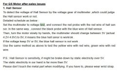
I came across a document today from QS Motors which explain how to test their motors hall sensor & found out it wasnt the same way I measured!
I was connecting multimeter negative probe to black wire in hall connector & posstive probe to each one of the 3 halls (YGB),
The results were 0v or 3.29v

QS document state that the Red probe of multimeter should be connected to the red wire of the hall connector & the black probe
to each of the halls (YGB) & I should measure either 0v or 5v. When tested the new 2000w motor that way I got on all 3 sensors 5v or 1.9v !!!
Is that means that all my 3 sensos are bad???

That might be the root cause for the cutoff
Thanks
 
Would you please post the link to that QS article. Also, if you post pictures of how you are metering it might help us understand what you are doing. Make sure they are in good focus.

:D :bolt:
 
Drupa said:
I disconnected the motor hall plug & measured the voltage on the controller side, results are as follows:

Black & red = 5.4v
Black to each one of the 3 sensors input (Yellow, Green, Blue) = 3.3v
That is unusually low; 5v is typical for the signal pullups, sometimes 12v or even more, depending on the system. I've never had a controller that only used 3.3v, but that's apparently how what you have is designed.

Whether it is the cause of the problem, you would have to test the system identically with the old motor and the new one first. If identical tests (same phase currents, same motor speeds, etc) work normally on both motors, then you would test with them both at higher and higher phase currents and speeds until you run into problems (which may well happen at different points on each motor). When you begin to have problems you can use an oscilloscope to then compare between the working and non working states, to see what kind of signal shape and noise you get at the failure points.

Knowing that, you could then figure out what causes it, and come up with something to help eliminate the noise if tha'ts cuasing it. Alternately you could just try some of the standard fixes, like capacitors on teh signal and power lines (from the signal to ground at the controller,, and the power to ground at the motor itself,


Reminder:
I made the voltage measurements on my no issues motor & got also 3.29v on Halls without any errors.
But you said your other motor isn't as fast as this one, nor is it being run at as high a power level. Thus electrical noise on the signal lines is less, and has less chance of affecting the controller's ability to read the signals, with the smaller/slower motor that works, vs the faster/bigger one that doesnt'.

What does it mean if the pull up is 3.3v?
It means the same thing I already said--the lower the voltage, the less difference between "off" and "on", and so the greater the chance of electrical noise in the system (of which there is a lot because it is a motor with constantly changing currents and switching voltages/currents) causing a problem.


There is the possibilty that the halls themselves in the motor that doesnt' work are simply not able to switch fast enough, or cleanly enough, so once the motor spins fast enough, the hall signal is simply not clean enough for the controller to "understand". You'd need an oscilloscope to see this. If this is the case, replacing the halls with ones better able to switch quickly, and ones that sink more current when "on" (which makes a more stable "zero"), might fix it.
 
Drupa said:
I came across a document today from QS Motors which explain how to test their motors hall sensor & found out it wasnt the same way I measured!
I was connecting multimeter negative probe to black wire in hall connector & posstive probe to each one of the 3 halls (YGB),
The results were 0v or 3.29v

QS document state that the Red probe of multimeter should be connected to the red wire of the hall connector & the black probe
to each of the halls (YGB) & I should measure either 0v or 5v. When tested the new 2000w motor that way I got on all 3 sensors 5v or 1.9v !!!
Is that means that all my 3 sensos are bad???

That might be the root cause for the cutoff
No, it's not that.

They are telling you to measure backwards from how anyone would normally do so--but the reason they tell you to do it this way is that "on" for a motor hall is the "0v" condition, and "off" is the "5v" condition.

The actual voltage difference between the two is the same either way (presuming the hall supply voltage is the same as the pullup voltage, which isnt' the case for your controller for whatever wierd design reason they had), but if you measure they way they tell you, you also have to "think upside down", and it's harder for most people to understand the results.

In either case, your sensors are switching correctly--whether they are switching fast enough, or fully grounding the signal at the faster speeds where your problem occurs, you would need an oscilloscope to see. A voltmeter or multimeter simply cannot show you problems like those.
 
@drupa: you should ask j bjork or bartosh to check this thread and measure their Votol hall voltages. I don’t have access to a votol currently. 3V just seems to low to get good function.

You can see what noisy hall signals look like here:
https://endless-sphere.com/forums/viewtopic.php?f=30&t=87305&hilit=Revolt+hall#p1274994
 
amberwolf said:
Drupa said:
I disconnected the motor hall plug & measured the voltage on the controller side, results are as follows:

Black & red = 5.4v
Black to each one of the 3 sensors input (Yellow, Green, Blue) = 3.3v
That is unusually low; 5v is typical for the signal pullups, sometimes 12v or even more, depending on the system. I've never had a controller that only used 3.3v, but that's apparently how what you have is designed.

Whether it is the cause of the problem, you would have to test the system identically with the old motor and the new one first. If identical tests (same phase currents, same motor speeds, etc) work normally on both motors, then you would test with them both at higher and higher phase currents and speeds until you run into problems (which may well happen at different points on each motor). When you begin to have problems you can use an oscilloscope to then compare between the working and non working states, to see what kind of signal shape and noise you get at the failure points.

Knowing that, you could then figure out what causes it, and come up with something to help eliminate the noise if tha'ts cuasing it. Alternately you could just try some of the standard fixes, like capacitors on teh signal and power lines (from the signal to ground at the controller,, and the power to ground at the motor itself,


Reminder:
I made the voltage measurements on my no issues motor & got also 3.29v on Halls without any errors.
But you said your other motor isn't as fast as this one, nor is it being run at as high a power level. Thus electrical noise on the signal lines is less, and has less chance of affecting the controller's ability to read the signals, with the smaller/slower motor that works, vs the faster/bigger one that doesnt'.

What does it mean if the pull up is 3.3v?
It means the same thing I already said--the lower the voltage, the less difference between "off" and "on", and so the greater the chance of electrical noise in the system (of which there is a lot because it is a motor with constantly changing currents and switching voltages/currents) causing a problem.


There is the possibilty that the halls themselves in the motor that doesnt' work are simply not able to switch fast enough, or cleanly enough, so once the motor spins fast enough, the hall signal is simply not clean enough for the controller to "understand". You'd need an oscilloscope to see this. If this is the case, replacing the halls with ones better able to switch quickly, and ones that sink more current when "on" (which makes a more stable "zero"), might fix it.

Thanks amberwolf for all your detailed answers.
I think I should clarify a bit since I might was misleading a bit.

The original motor is 1000w inrunner with smaller diameter compared to the new 2000w motor, however I think I might gave the wrong impression about it performance.
The 1000w does reach 10k RPM but with less torque compared to the new one. when I said slower or weaker I was making a referance to the bigger motor & not beacuase the original motor is weak compared to other motors.
I actually cant even tell if the new motor reached the same or higher RPM since from day one the I couldnt read proper RPM above approximtlly 2.5k RPM.

Where I felt the difference was when the wheels were in the air with full throttle with both motors & the torque I felt while sitting on the Quad & applied the throttle from dead stop.


P.S - Which capacitors value should I use on both motor power & hall Signals

Thanks
 
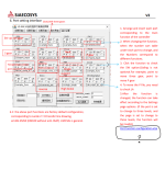
Does anyone know how to get the excel file of the Port Configuration Setting?
I cant reach that link from any download soure


Thanks
 

Attachments

  • Port Setting..PNG
    Port Setting..PNG
    113.6 KB · Views: 1,641
QS Motor Hall Sensor Test

QS Motor Hall Sensor test.JPG
 
Drupa said:
Does anyone know how to get the excel file of the Port Configuration Setting?
I cant reach that link from any download soure

You won’t need it to get this fixed.. but you can ask QS for it. Judy@tzquanshun.com
Please upload it if you get it.
 
larsb said:
Drupa said:
Does anyone know how to get the excel file of the Port Configuration Setting?
I cant reach that link from any download soure

You won’t need it to get this fixed.. but you can ask QS for it. Judy@tzquanshun.com
Please upload it if you get it.
Its not for the Hall issue its for the attempt to operate the reverse on my EM-50s on the test bench (The process isnt clear at all)
Also tried to rcover from the throttle Hall fault by checking wires, voltage & Settings.

All seems OK but cant clear the error

While Throttle is connected without rotating it, I get
Red & Black 5.3v
Black & Green (Signal) 0.85v

At Full throttle
Black & Green (Signal) 4.55v

My Controller settings are ok but still getting the error :confused:
 

Attachments

  • Throttle settings.PNG
    Throttle settings.PNG
    12.8 KB · Views: 1,626
I just bought Votol EM100 and plugged into my Chinese 1500 Watt BLDC motor. I face the same problem with the hall sensor fault message. After check with multi tester, measurement result as below :
Power + (red) and - (black) : 5.46 V
Red probe to power + and black probe to either yellow, green or blue wire and move the motor slowly with hand : variation between 2.6 V - 5.2 V.
After googling I found the fact that my Chinese motor hall sensor type is linear type (analog). In further googling I found that QS motor (which is match with Votol EM 100) uses bipolar type (digital).
As we know, there are 3 types of hall sensor :
1. Analog - Linear which pass the voltage variably based on how far the negative magnet pole from the sensor.
2.1 Digital - Bipolar, on or off based on which magnet pole approaching the sensor.
2.2 Digital - Unipolar almost same with Linear type but can only on and off.

I'm going to change the hall sensor to Bipolar type as attached to many QS Motor, and will inform the result soon.

Cheers.
 
Hi bhagudunk,
And welcome to the forum! :)

The results of your testing might seem a bit different from what you might read about. As typically the outputs are checked with the BLACK test probe on ground or negative wire. With the RED lead probing the outputs of the hall sensors.

If my math is correct, that would seem to indicate that the sensor would be toggling between 2.6vdc and 0vdc.
The 2.6vdc would seem a bit low, typically 3vdc and above... I'd be curious what the voltages are from all three hall sensor signal outputs from the controller with the connector undone.

Please share what the hall sensor part numbers are that you intend on replacing, to let others know what to look for.

For alternative motor hall sensor testing, I.G. without using controller for power or electronic signals... see this thread.
https://electricbike.com/forum/foru...-motor-s-phase-wiring-hall-sensors-and-wiring

Here is a collection of other hall sensors that have been used or recommended for motor sensing use. And their operational characteristics. All three being bipolar.


Checking the Operational Characteristics of the three recommended types.


Sensor____ Gauss OPEN____ Gauss CLOSE____ Gauss Differential____ Min voltage____ Max voltage

SS411A________ -60________________ 60____________________ 15_________________ 3.8vdc__________ 30vdc__________
OEM installation.
SS413A________ -140______________ 140___________________ 20_________________ 3.8vdc__________ 30vdc__________ Recommended by Grin.
SS41G_________ -140______________ 150___________________ 40_________________ 4.5vdc__________ 24vdc__________
Thread recommendation taken from internet thread posts.


Note: Gauss values @ 77 degrees.


Reference Datasheets...
https://prod-edam.honeywell.com/cont...iid-143161.pdf
https://www.mouser.com/datasheet/2/1...ns-1894281.pdf

EDIT: Corrected bad links. :(


Good luck with the new replacements! Stop back with news of your success!


Regards,
T.C.
 
Hi TommyCat,

Yes you are right, connecting black probe to ground wire and red probe to output wire resulting voltage between 0V - 3.3V.
Current hall sensor installed is A3144 (linear type) and I already bought 41F type (bipolar) from local online marketplace.
Is it OK with this type?

Note : current hall sensor works well with my old China 45 amps controller but reported faulty with my new Votol em100.

My motor is 72 V 1500 W hub motor with 24 pole pair and 52 magnet pole, 120 degree hall shifting, double layer winding modified from Star to Delta.
Windings : modified from
14 x 0.5mm, 6 turn per pole to
20 x 0.5mm, 4 turn per pole.
to achieve higher current.

Please suggest what the best think to do..

Thanks
 
The only motors I've worked with that used analog-output (rather than switching) hall sensors did not use the UVW (three halls) sensor type, but rather used a SIN/COS encoder, with only two halls, and a separate magnet ring (around the axle area) to do position sensing.

All of the motors I've worked with that used UVW (three halls) sensor type used switching (usually latching bipolar like the Honeywell S411 or S41) hall sensors.

It doesn't mean that yours is the same as either of the above, but it'd be the first one I've seen like that.


One reason for using the switching type of sensor in the UVW type motors/controllers is they can be made more immune to noise, as the signal isn't "generated" by the motor and sent to the controller, it's only grounding a voltage placed on the signal line by the controller, which could, if needed, be a fairly high voltage (up to 30v on some of them), though they often use only 5v; 12v on some of the higher power controllers (because the higher the voltage on the signal lines, the greater the difference between on and off states, and so the easier it is for the controller to be *sure* of what the signal is, and the more accurate it's position info is even in electrically noisy conditions).

An analog-output sensor can only output a very small and specific voltage range for a specific magnetic field strength variation, and they usually use a "center off" configuration--about half the total voltage supply output when no magnet is present, and go not quite to either the positive supply rail voltage or ground when full magnet strength is present, with north polarity going one way, and south the other, so they don't even output the full voltage range.

This signal is thus smaller and more susceptible to noise than the digital output version, and since the signal type will be on/off anyway, there's no reason to use this kind of sensor except for systems that use analog position sensing like SIN/COS.
 
:flame: :flame:
Drupa said:
Hi All

New update:
I came across a document today from QS Motors which explain how to test their motors hall sensor & found out it wasnt the same way I measured!
I was connecting multimeter negative probe to black wire in hall connector & posstive probe to each one of the 3 halls (YGB),
The results were 0v or 3.29v

QS document state that the Red probe of multimeter should be connected to the red wire of the hall connector & the black probe
to each of the halls (YGB) & I should measure either 0v or 5v. When tested the new 2000w motor that way I got on all 3 sensors 5v or 1.9v !!!
Is that means that all my 3 sensos are bad???

That might be the root cause for the cutoff
Thanks

Thanks amberwolf for the lesson, this will be a very key understanding that all member should know.
QS document stated above clearly indicate that QS Motor (which is the best match of Votol controller) using bipolar hall sensor that give 0V (off) and 5V (on) output.

Back to the ground, one thing I still don't know is whether I have to use 10K resistor soldered to +5V and the output leg of each hall sensor or not.
I guess the controller has this component attached internally.
Anybody has experience on this, please let me know.
 
Back
Top