MXUS 3000 Hub Motor - V1 V2 V3

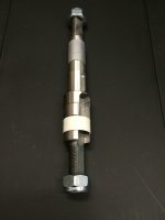
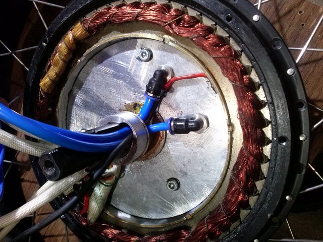
btw, i'm a bit afraid if the 10x14mm axle is sufficient for the power many here will pump into the motor, so asked MXUS what kind of steel its made of. they answered its "45# steel alloy".
this could be C45 steel or 45CrMo but i guess the latter which would be not bad (42CrMo4 or 45CrMo4 has >900N/mm² yield strength).
 
Is there anybody selling these in the us V2 5 turn?
I only read till page 9 or so.
My bike is a fat tire 29" OD and I think the 5 turn would suit it better plus the v2 is just better.
I found a v1 4 turn on ebay teslanv is selling. Shipped to me would be just under $400.
Should I just bite on this one?
 
Better hurry, the Mrs is stubborn here but softening up...
 
ElectricRiding said:
where can these be bought individually?
ebay, aliexpress, alibaba, etc.
http://www.aliexpress.com/item/MXUS-45mm-magnets-high-powerful-motor/2043119619.html
 
Ordered an upgraded axle from Linukas that has dual slots, one for heavier gauge wires and the other for the liquid cooling lines. He said this was a lower quality milling than another option he has, but he indicated he has used it on numerous bikes with no problems. It looks much better than the standard axle to me. I still need to have the side cover milled on one side to except the new larger 42mm OD x 32mm ID bearing. I have ordered and received new 12 gauge phase wires, from Turnigy that have a silicone jacket that is rated to 200C. Easily could have fit 10awg wire, but I did not see the reason based on the currents I will be running. Additionally I wanted the wires to have plenty of space to make assembling the motor easy. These are basically the same wires that come from the Lyen controller, so a good match and I was able to get the Blue, Yellow and Green to match the controller.

I also ordered the cooling lines TIG welded to the thin copper plate that will draw the heat away from the motor. The photos only show one loop, but Linukas actually sent two of these. I plan on placing Swagelok fittings with a barbed adapter to connect the actual soft lines to cut down on the possibility of leaking. I think the parts from Linukas were well worth what I paid for them. Placed some photos below if you're interested. Will update as things come together hopefully before January is out. Also, plan on taking the dimensions of the axle and drawing up a CAD file in Sketchup so I can share it here. Linukas had said he was ok with this in an earlier post. I want to thank Linukas for working with me on this and his willingness to answer my questions and get the parts to me. The water pump I plan on using will use minimal power and theoretically should not need to be turned on often, mainly when I am climbing hills that are 3 miles long where heat buildup becomes an issue. This should be very effective for removing heat from the motor in a short period of time. Time will tell.

Ed
 

Attachments

  • Dual-openings.jpg
    Dual-openings.jpg
    59.1 KB · Views: 3,070
  • Linukas-Axle.jpg
    Linukas-Axle.jpg
    47.8 KB · Views: 3,070
  • Cooling-loop.jpg
    Cooling-loop.jpg
    83.6 KB · Views: 3,070
  • Cooling-loop-2.jpg
    Cooling-loop-2.jpg
    55.4 KB · Views: 3,069
Finished drilling my spoke holes about 2 weeks ago, but just have time now to post some of the photos. I think they came out ok, although the jig I had made was a little off, so the holes are not centered in the lip of the motor as well as I would have liked, but it should work fine. I opted for the 13 awg spokes due to problems I have had with 12 awg in the past. I may find out the 12 awg is better, but I can always enlarge these holes if necessary. I used a 2.8mm drill bit and a small countersink bit to create the tapered opening. I also shorted the phases wires, "using an alligator clip" as I was drilling because the electric braking of this motor was very effective and could hold the motor still while drilling. You can see the clip in some of the photos. I was also able to drill, with the side covers left on so I did not have to worry about metal shavings getting inside of the motor. In one of the photos you can see the cutting oil that I had used to avoid dulling the bit and also to allow for cleaner cutting of the holes.

Ed
 

Attachments

  • Drilling-Spoke-Holes.jpg
    Drilling-Spoke-Holes.jpg
    104.5 KB · Views: 3,056
  • Completed-13 Gauge Spoke holes.jpg
    Completed-13 Gauge Spoke holes.jpg
    103 KB · Views: 3,056
  • Closeup of new spoke hole.jpg
    Closeup of new spoke hole.jpg
    84 KB · Views: 3,056
Nice cooling kit. Make sure you do a thread on that motor and cooling kit. I am sure many more then I would like to follow that.

What version of the motor do you have?
Reason for asking is that AFAIK copper and aluminum don't mix well, the result will be galvanic corrosion and something will give.
You might wanna look into getting a non-conductive adhesive to attach that copper cooler. And think about what material you choose for your radiator as the liquid itself can act as an electrical transfer.

Other then that I am really excited to see how your kit turns out.

What kind of voltage and power are you targeting with your setup? I guess with that serious cooling kit heat will not be an issue for you. Are you gonna run temp sensored fan for the radiator to avoid heat build up if caught up in a red light for too long?


*Subscribed*
 
Holee$h!t Edventure, where did you come from with this MXUS mod? One word, AWESOME! So tell us a little about the build its going on.
 
edventure said:
Ordered an upgraded axle from Linukas that has dual slots, one for heavier gauge wires and the other for the liquid cooling lines. He said this was a lower quality metal and machining than another option he has, but he has used it on numerous bikes with no problems. It looks much better than the standard axle to me. I still need to have the side cover milled on one side to except the new larger 42mm OD x 32mm ID bearing. I have ordered and received new 12 gauge phase wires, from Turnigy that have a silicone jacket that is rated to 200C. Easily could have fit 10awg wire, but I did not see the reason based on the currents I will be running. Additionally I wanted the wires to have plenty of space to make assembling the motor easy. These are basically the same wires that come from the Lyen controller, so a good match and I was able to get the Blue, Yellow and Green to match the controller.

I also ordered the cooling lines TIG welded to the thin copper plate that will draw the heat away from the motor. The photos only show one loop, but Linukas actually sent two of these. I plan on placing Swagelok fittings with a barbed adapter to connect the actual soft lines to cut down on the possibility of leaking. I think the parts from Linukas were well worth what I paid for them. Placed some photos below if you're interested. Will update as things come together hopefully before January is out. Also, plan on taking the dimensions of the axle and drawing up a CAD file in Sketchup so I can share it here. Linukas had said he was ok with this in an earlier post. I want to thank Linukas for working with me on this and his willingness to answer my questions and get the parts to me. The water pump I plan on using will use minimal power and theoretically should not need to be turned on often, mainly when I am climbing hills that are 3 miles long where heat buildup becomes an issue. This should be very effective for removing heat from the motor in a short period of time. Time will tell.

Ed

Nice that you got my package, but you little bad understood my explanation about axle, it is made of good quality steel, but it milling finish is not perfect.
 
Nice that you got my package, but you little bad understood my explanation about axle, it is made of good quality steel, but it milling finish is not perfect.

Hi Linas,

Sorry about the misunderstanding, I will edit the post to correct the explanation. I think the quality is excellent regardless, it would cost considerably more here in the US to purchase one of an equivalent quality and they would probably want a minimum order of a 100+ . I measured the diameters of the bearings seats on the axle and they are very close, may need to just clean it slightly, so not too concerned.

Also, are you ok with me taking the dimensions of the axle and converting it into a CAD drawing to share here? If not, no problem. I will still need to find the time to do it anyway.

Thanks again and maybe you can get some US business going if this works out.

Ed
 
macribs said:
Nice cooling kit. Make sure you do a thread on that motor and cooling kit. I am sure many more then I would like to follow that.

What version of the motor do you have?
Reason for asking is that AFAIK copper and aluminum don't mix well, the result will be galvanic corrosion and something will give.
You might wanna look into getting a non-conductive adhesive to attach that copper cooler. And think about what material you choose for your radiator as the liquid itself can act as an electrical transfer.

Other then that I am really excited to see how your kit turns out.

What kind of voltage and power are you targeting with your setup? I guess with that serious cooling kit heat will not be an issue for you. Are you gonna run temp sensored fan for the radiator to avoid heat build up if caught up in a red light for too long?


*Subscribed*
Hi Macribs,

This is a version 1 motor that was part of the US group buy handled by Teslanv.

I am still trying to decide what the best adhesive will be to thermally connect, "not electrically" the copper loop to motor stator. Any recommendations will be greatly appreciated. I am sure there are many options out there that could serve this purpose. I will probably use some type of CPU or even possibly a small dirt bike radiator, but I am not sure if these are made from aluminum or copper, but you do have a good point here. I think if I use a good radiator fluid like for automotive use there are corrosion inhibitors within the fluid that should minimize this problem, but I will look into this before making a final decision.

Currently I my battery is only a nominal 48V 30aH pack in a 16s2P configuration. When fully charged about 54V. I would like to bring to a 72V configuration, but this will need to wait until after I finish the motor mods due to funding. My problem is I have a 20 mile ride to work one way that includes almost a 1000 ft of elevation gain during the ride. I had a Crystalyte motor that I had fried after a little more than 1800 miles. I was going to rewire that motor with a higher temp wire and try to add cooling, until this motor came along. Here is the link so you can see what happened to that motor and why I am doing this. I probably, "as many people would state" had the controller tuned to drive too much current/power to the motor, but where I had it tuned it worked very well, especially on hills. One of the problems was I had my block time set to more than a second so the peak wattage at many points would run up to 2600 Watts for more time than was appropriate for this motor, which is way too much for that Clyte motor especially when driving 20 miles constantly at 30 MPH plus. I am hoping, with a combination of this new motor being more beefy to start plus the cooling, I should have no problem with overheating and can hopefully pull 30K miles from it.

I am going to run with no fan to start to try and cut down on the required power. When sitting at a light the motor should not continue to heat up and just the action of the liquid pumping through the radiator should still remove heat from the motor. I may decide later to include a fan. I was thinking of possibly running the pump to a comparator circuit that would monitor the temperature of the motor and only kick on the pump if it got above some preset temp. I may first just include a switch, but I am changing things as I go along here.

I will copy some of this to a new thread sometime this weekend so I can separate it from this thread. I will place a link here once I do in case anyone wants to follow.

Thanks for the feedback,

Ed
 
Rix said:
Holee$h!t Edventure, where did you come from with this MXUS mod? One word, AWESOME! So tell us a little about the build its going on.
Hi Rix,

This mod was actually supplied from user Linukas who is in Lithuania. I wish I could say it was my design and idea, but he had posted in one of the earlier threads that he had modified one of the MXUS motors to include liquid cooling. I PM'd him and asked if he would be willing to sell the axle and cooling loops and he did to hesitate. I think he would be willing to sell multiple kits to someone here in the US if they wanted to modify the MXUS motors and resell them. He is also willing to sell an already modified motor with 8AWG phase wires and the liquid cooling for around $420 Euros which is about $500 US dollars. If I knew this earlier I may have just purchased a motor from him, but this should be a good learning experience. Here is a link to his original post regarding his cooling mod. http://endless-sphere.com/forums/viewtopic.php?f=2&t=63142&hilit=Linukas&start=225

I will post a new thread to update as I go along and link to it here.

Best,

Ed
 
edventure said:
Nice that you got my package, but you little bad understood my explanation about axle, it is made of good quality steel, but it milling finish is not perfect.

Hi Linas,

Sorry about the misunderstanding, I will edit the post to correct the explanation. I think the quality is excellent regardless, it would cost considerably more here in the US to purchase one of an equivalent quality and they would probably want a minimum order of a 100+ . I measured the diameters of the bearings seats on the axle and they are very close, may need to just clean it slightly, so not too concerned.

Also, are you ok with me taking the dimensions of the axle and converting it into a CAD drawing to share here? If not, no problem. I will still need to find the time to do it anyway.

Thanks again and maybe you can get some US business going if this works out.

Ed

here is CAD drawing, it is simple with no accurate dimensioning, this axle fit to V1 motor, I do not know if it fits to V2 because do not have it. as for cooling, I made some cooling modifications for middle version of cromotor, or better to name it manufacturer name: QSmotor, it have very similar aluminum stator part and here is how I modified it to liquid cooled :
UXeEVLsl.jpg

it stator is little milled to make small corner and on it in both sides added aluminum laser cut sheets, all corners are sealed with engine class silicone, and both sheets are fastened together with 3 screws. to make liquid circulate each (one is not milled that is from one to other pipes to circulate round the stator) of stator legs have small grove to make space to aluminum cover. this design works ok, just at first needs good bleeding, it works better than mxus v1, but cost more and are more sensitive for bleeding.
 

Attachments

  • axle.dwg
    68 KB · Views: 92
Interesting. I'm going to get my MXUS build completed first, then get some sort of temperature data monitor, tapped into the controller and supplied thermistor. So as to first see what temperatures I may be driving the motor to. Its not just the motor though, but the controller and battery too. And if temperatures are ranging too high, then the cooling system must account for its source. We need more data on the MXUS 3000 performance in all respects, including actual temperature ranges, in use. And to what degree these temperatures might be destructive of components.
 
What am I missing here. If you only needed 2600W peak for that 20 mile ride, why would you think you needed extra cooling for a 3000W rated motor? 1000 ft. elevation over 20 miles is less than a 1% grade. This motor should do 1000 ft. rise in 1 mile, which is only about a 20% grade. I haven't riden mine much because it was too uncomfortable with the stock handelbars, and now the weather has been too cold for me the last week or so, but running 24s 40A on it doesn't seem to phase it even on 29" diameter fat tires.
 
the cooling kit for the Cro is awesome. great idea and job^^
Linas, i have V2 3T motor and will take it apart the next days and do some measurements. i can give them to you if you want so you could fabricate V2 axle :)

As i definitely want to upgrade the axle, i will design my own one for 150mm dropout without the need for c-washers. a buddy has promised me to fabricate it out of 42CroMo4 steel. I guess he makes it on CNC machine so i could ask for more pcs if there is some interest. the bad thing is the sidecover also needs to be machined for the bigger bearing..
 
The 3T winding should be able to handle over 300A of phase current. It's can handle 40% more current than the 15X4 motor that was tested at the beginning of the thread, just based on the stand counts. And that 4T motor was running at 250 Phase amps, with no cooling system. (Although that was for a momentary sprint)

I would suggest running your 3T motor with a temp monitor first to see how well it does before spending time and money on cooling it. Really, it's just the phase wires and controller you need to worry about overheating, unless you are trying to push 15+Kw through this motor.

Upgrade the phase wires to 10AWG or 6mm2 first, IMO.
 
Pushing it with 10kw and 300phase amps will get the motor overheated in no time, 5minutes, tops.
Below:
7000watt, 30secons=over 100°C on the windings. I don't think phase wires are the main concern here.
[youtube]rD6IF2spm-Q[/youtube]
 
Allex said:
Pushing it with 10kw and 300phase amps will get the motor overheated in no time, 5minutes, tops.
7000watt, 30secons=over 100°C on the windings. Idon't think phase wires are the main concern here.
[youtube]rD6IF2spm-Q[/youtube]
That's the 4T Wind. Not the 3T. The 3T is capable of handling 40% more phase amps, barring the phase wires overheating. This is because the 3T has 21 strands of copper around each stator tooth, as compared to the 15 strands of the 4T that is in the videos. This results in a cross-sectional area of winding that is 40% greater, and thus 40% more capable of handling current. The limitation is only the phase wires, which if you upgrade to 10AWG or 6mm2 would net you more than double the current handling of what the 4T wind comes with stock. (2.5mm2)

Here is a nifty chart that shows the comparison between the windings and how they handle phase current:

teslanv said:
21x3-Turn Wind (12 Kv): 240A --> (11.43A per strand)
16X4-Turn Wind (9 Kv): 180A --> (11.25A per strand)
12x5-Turn Wind (7.2 Kv): 144A --> (12.00A per strand)
10X6-Turn Wind (6 KV): 120A --> (12.00A per strand)
9X7-Turn Wind (5.1 Kv): 103A --> (11.43A per strand)
8X8-Turn Wind (4.5 Kv): 90A --> (11.25A per strand)
7X9-Turn Wind (4 Kv): 80A --> (11.43A per strand)
6X10-Turn Wind (3.6 Kv): 72A --> (12.00A per strand)
5X12-Turn Wind (3 Kv): 60A --> (12.00A per strand)
 
I would want to see this kind of run with 3T, sure it will take longer time to heat it up to 100°C but not by many seconds. I would be glad if proven wrong.
 
Back
Top