Some notes:
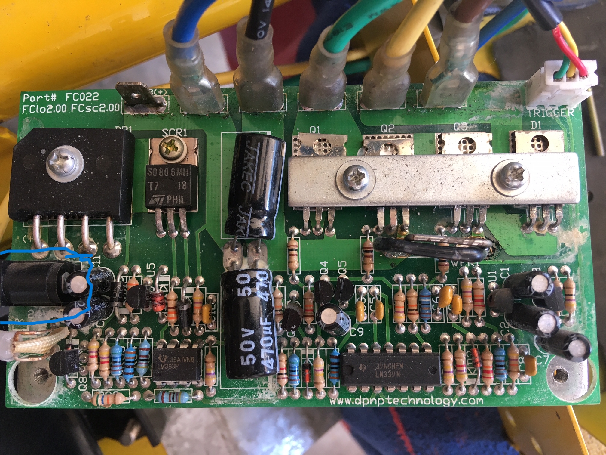
I can't do a complete analysis of the circuits on that board, especially because I can't see both sides so many traces are not visible, and a number of small transistor-style components' markings aren't visible, but the right half looks like a typical analog-type brushed motor controller.
Note that the LM339 chip that runs (is) the controller typically has a max voltage allowable of only 30v. Same for the LM393 over on the left side. How long they will last at the higher voltage, I don't know. There may be a zener-diode+resistor "regulator" (voltage limiter, really) but it's resistor is likely calculated for the original voltage, so the current to the zener may be higher than allowable for the desired output, and it may either not limit properly or it may fail and then suddenly allow full voltage to the chip when it does (which would then cause the chip to fail).
LM393
Supply Voltage - Min: 2 V
Supply Voltage - Max: 30 V
Operating Supply Current: 225 uA
Minimum Operating Temperature: 0 C
Maximum Operating Temperature: + 70 C
LM339
Vs (Max) (V) 36
Vs (Min) (V) 2
Operating temperature range (C) 0 to 70
It's hard to tell for sure, but it looks like someone has bypassed the current-limiting / circuit-protection shunt (the smaller straight bare wire on "top", toward the FETs) with a piece of black-insulated wire; if so this prevents the controller from protecting itself against overcurrents, and can cause sudden unexpected failure. Failure of brushed motor controllers usually means it is stuck on, so the motor then runs at full speed and can't be stopped except by unplugging it or the battery from the controller. (or otherwise disconnecting power from the system).
FWIW, http://4qd.co.uk has a learning section that has a fair amount of brushed motor controller info, including schematics and discussion of their older 2QD versions that are similar to this controller, if you want to learn how they typically work.
")
A good starting page: https://www.4qd.co.uk/docs/what-is-pwm/
The left half looks like a comparator setup most likely to show charge state via the red/green LED at the left edge.
It may possibly also be to disconnect the system (via the SCR; not sure how they turn it off, or if they use it as a crowbar to blow an inline fuse somewhere (not visible)) in case of battery undervoltage/overvoltage and/or possibly for controller overcurrent conditions.
Not sure why the rectifier (biggest thing in the top left corner); perhaps the original charger is just 24VAC (the marking next to the connector sort of looks like it says this), so it just rectifies it and then feeds it into the lead-acid battery, which thru it's internal resistance/capacitance smooths this out into the necessary charging conditions.
At any rate, it's likely that none of that leftside circuitry is relevant to your 36v lithium battery (unless it includes controller-circuit protections), and so you should probably just charge that battery directly at it's own charge port so it's BMS can do it's job without interference from outside. If there *are* controller protections built into the circuitry, they probably act on the B+ or B- tabs at the edge of the board where the battery's discharge connector plugs in, anyway. (and not the charger port).