
Hi,
I'd like to add a second battery (36V Li-ion) to my ebike to increase its range. My goal is to use one battery at a time, not using both in parallel with e.g. ideal diodes or something. I'd like to keep it as simple and as safe as possible and just use a 2 way switch to choose which battery the motor will pull current from. My 36V ebike motor draws about 20-25 A max so I figured out it would be best to use 2 N-channel mosfets to control which battery is being used. The N channel mosfets I plan to use are rated for 80V, 150 A and have a resistance from drain to source (RDS) of only about 3 milliohms (see https://www.mouser.ch/datasheet/2/427/sup60020e-1595623.pdf). This means at 25A the mosfet will dissipate 1.875 W. This should be okay without heat sink because the mosfet can be used without heatsink up to 3.5 W at an ambient temperature of 35°C.
I'm a noob in electricity/electronics so I tried to educate myself about mosfets and came up with the following circuit:
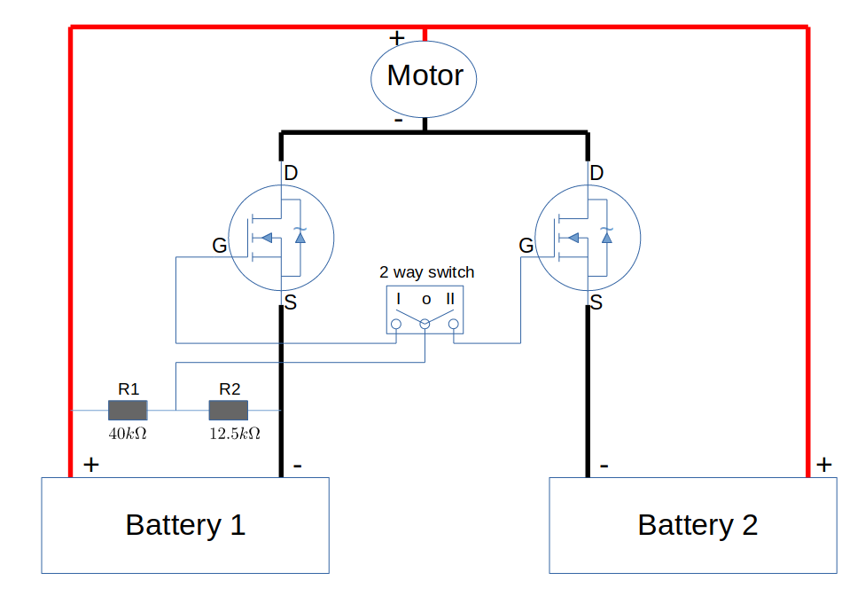
The idea is that when the switch in the center of the diagram is in the I position, battery 1 will power the motor. on the other hand, when the switch is in the II position, battery 2 will power the motor. However battery 1 will always be on the bike so it would be used to control the gate on the mosfets. The two resistors R1 and R2 are used as a voltage divider in order to drop the input voltage of battery 1 from 36V down to about 10 V in order to power the gate of the 2 mosfets since these mosfets have a max voltage from gate to source (VGS) of 20 V.
Now I have a few questions about this circuit:
1) when the switch is e.g. in position I, the mosfet on the left will allow the motor to run from battery 1. However, this also closes the path from the positive terminal of battery 2 to the negative terminal of battery 1...meaning that the motor would also be running from battery 2 as well. Is that correct?? The same occurs when the switch is in position II. This allows battery 2 to run the motor but the positive terminal of battery 1 becomes connected to the negative terminal of battery 2 so that the motor would also be running from battery 1 at the same time. Does this mean there is a huge issue with my circuit?
2) What happens if the two batteries don't hold the same charge e.g. battery 1 is at 30 V and battery 2 is fully charged at 42 V? I want to use a switch to properly isolate each battery from the other (I don't want to run the 2 batteries in parallel with e.g. ideal diodes). Would this circuit allow any cross-current to flow from the battery with the highest charge to the battery with the lowest charge? In other words, is it safe?
3) Should I be concerned with voltage spikes and inrush current when switching either battery on? What should I do to prevent such inrush currents from damaging parts in the circuit (above all, I want to avoid any damage to occur on the Motor controller and battery BMS)
4) Any change recommended on that circuit?
Thanks a lot for your help!
I'd like to add a second battery (36V Li-ion) to my ebike to increase its range. My goal is to use one battery at a time, not using both in parallel with e.g. ideal diodes or something. I'd like to keep it as simple and as safe as possible and just use a 2 way switch to choose which battery the motor will pull current from. My 36V ebike motor draws about 20-25 A max so I figured out it would be best to use 2 N-channel mosfets to control which battery is being used. The N channel mosfets I plan to use are rated for 80V, 150 A and have a resistance from drain to source (RDS) of only about 3 milliohms (see https://www.mouser.ch/datasheet/2/427/sup60020e-1595623.pdf). This means at 25A the mosfet will dissipate 1.875 W. This should be okay without heat sink because the mosfet can be used without heatsink up to 3.5 W at an ambient temperature of 35°C.
I'm a noob in electricity/electronics so I tried to educate myself about mosfets and came up with the following circuit:
The idea is that when the switch in the center of the diagram is in the I position, battery 1 will power the motor. on the other hand, when the switch is in the II position, battery 2 will power the motor. However battery 1 will always be on the bike so it would be used to control the gate on the mosfets. The two resistors R1 and R2 are used as a voltage divider in order to drop the input voltage of battery 1 from 36V down to about 10 V in order to power the gate of the 2 mosfets since these mosfets have a max voltage from gate to source (VGS) of 20 V.
Now I have a few questions about this circuit:
1) when the switch is e.g. in position I, the mosfet on the left will allow the motor to run from battery 1. However, this also closes the path from the positive terminal of battery 2 to the negative terminal of battery 1...meaning that the motor would also be running from battery 2 as well. Is that correct?? The same occurs when the switch is in position II. This allows battery 2 to run the motor but the positive terminal of battery 1 becomes connected to the negative terminal of battery 2 so that the motor would also be running from battery 1 at the same time. Does this mean there is a huge issue with my circuit?
2) What happens if the two batteries don't hold the same charge e.g. battery 1 is at 30 V and battery 2 is fully charged at 42 V? I want to use a switch to properly isolate each battery from the other (I don't want to run the 2 batteries in parallel with e.g. ideal diodes). Would this circuit allow any cross-current to flow from the battery with the highest charge to the battery with the lowest charge? In other words, is it safe?
3) Should I be concerned with voltage spikes and inrush current when switching either battery on? What should I do to prevent such inrush currents from damaging parts in the circuit (above all, I want to avoid any damage to occur on the Motor controller and battery BMS)
4) Any change recommended on that circuit?
Thanks a lot for your help!