
I modified an existing BLDC design posted previously on E.S. by Jeremy Harris. I had a few questions regarding the layout that I was hoping someone could answer:
1. Currently, all layers are 3oz copper and my layer stackup is:
- Top: VCC_BATTERY, connection from mosfet driver to mosfet gates
- 2nd: GND
- 3rd: Signals from external microcontroller, VCC12v0
- Bottom: FETS, misc.
"FETS" is the net name connected to the source pin on the low-side MOSFETs. "FETS" is connected to GND through a .005 ohm shunt resistor. Do you think it would be best to place "FETS" or GND on the bottom layer of the board (in regards to signal integrity and heat dissipation)?
2. I've used polygons throughout the board instead of narrow traces. I think they are large enough to dissipate heat and ensure signal integrity, but please let me know if this is not the case.
Thank you!
View attachment Board and Schematic.zip
Schematic:
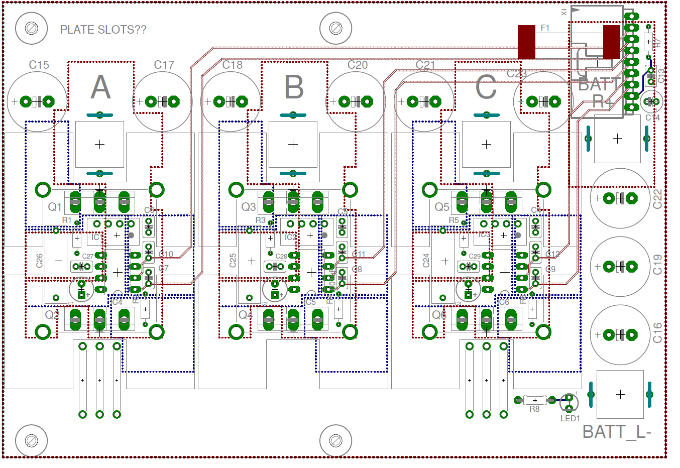
Board:

1. Currently, all layers are 3oz copper and my layer stackup is:
- Top: VCC_BATTERY, connection from mosfet driver to mosfet gates
- 2nd: GND
- 3rd: Signals from external microcontroller, VCC12v0
- Bottom: FETS, misc.
"FETS" is the net name connected to the source pin on the low-side MOSFETs. "FETS" is connected to GND through a .005 ohm shunt resistor. Do you think it would be best to place "FETS" or GND on the bottom layer of the board (in regards to signal integrity and heat dissipation)?
2. I've used polygons throughout the board instead of narrow traces. I think they are large enough to dissipate heat and ensure signal integrity, but please let me know if this is not the case.
Thank you!
View attachment Board and Schematic.zip
Schematic:
Board:
")