New Crystalyte Motor series (HT35 / HS35 and HT24 / HS24)

I am still running a HT 3525 at 24S lipo 60amps. Cut myself some cooling holes and she's still doing great no issues.

Probably have 1500 miles on her by now. I even noticed last night on methtek.com that the prices are dropped about 100$ since
I bought mine.
 
I sure am nicobie.

I replaced halls once and painted my copper with an insulator.

Need to get th 5404 going so i have something to compare.

My macs just cant take this kind of abuse.
 
I have 615 miles on mine running 20s at 40 amps. Runs like a charm Nothing needs replacing yet, know on wood. I'm also quite surprised with the torque! It blasted up the steepest hill I could throw at 30 mph. :mrgreen:
 
Can anyone help me with a question?

I have an hs3540, an 18 fet controller, and a 22s lipo pack. How much power can this setup deliver with the controller unlimited? I ask because I'm only seeing 60a peaks and I suspect something is wrong.
 
auraslip said:
Can anyone help me with a question?

I have an hs3540, an 18 fet controller, and a 22s lipo pack. How much power can this setup deliver with the controller unlimited? I ask because I'm only seeing 60a peaks and I suspect something is wrong.
Yeah looks like your controller has something wrong with it.... I would sell it ASAP

Just kidding! :mrgreen:

Looks like your motor is getting nice and comfy running that voltage.
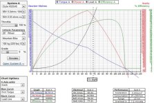
If you set up the ebikes.ca simulator for your motor, set up the voltage to 92.4, and set the controller to 100 amps and its in a 26 inch wheel. You will find the motor, at start up will suck in all the amps it can from the controller, but as the motor starts to get up to speed it hits a point where the power, the motor needs to accelerate goes down, drastically. The simulator puts the amp draw, at that 92.4 volts, at around 60 amps. Nothing to worry about. :mrgreen:

As far as the explanation goes, I am still learning this as well :mrgreen:
 
The stock 18 fet controller is configured to limit power at 60 battery amps. situation normal.

If you modify the controller you can allow the controller to pass more current but pushing a system close to it's limits means higher chance of magic smoke.. 60 amps is proper and more than enough to get you in trouble. :wink: .. but reliable.
 
Thanks for the responses guys. Something must be wrong with my controller! I have soldered the shunt up, and it's still only pulling 60a. (peak is a bit higher)

In the ebike.ca sim It shows I should be able to do almost 12kw, but instead I'm sitting at 5kw.
 
auraslip said:
In the ebike.ca sim It shows I should be able to do almost 12kw, but instead I'm sitting at 5kw.

Did you notice the efficiency at that peak 12kw...probably about 50%, so the motor wouldn't last long at all. What is your peak current set to in the CA? Maybe that's the cause. Also, there's a much better way than just slapping solder on a shunt.
I demonstrate a simple way here http://endless-sphere.com/forums/viewtopic.php?f=2&t=31643&p=458366, and Bigmoose also shows us a more elegant way in the same thread. There's also a more recent thread with more info about using a voltage divider.

John
 
Yeah the 18 fet controllers are actually set/advertised as 50a out of the box. It' weird that you're not seeing more than that though if you've soldered up the shunt. Especially with a HS motor at that voltage. With the HT I could understand it, because they're actually fairly efficient and don't suck much current. I soldered/wired the crap out of a shunt a while back after after testing a (then) new 8x8 9C and finding it wouldn't draw over 60 amps. In the end I figured there was something wrong with the controller until I hooked it up to a 9x7 9C and found it then drew 120 amps.

John, when hardware modding shunts I do something similar with strands of copper only I have them wider off the shunt in a U shape and somewhat fanned out. I start off with higher current than wanted for a given number of strands for the gauge of the wire then snip through each strand to fairly accurately lower current in steps. Doing it in the software is easier if you have a programmable controller but this isnt always an option.
I've also tried playing with the shunt bias resistor ( was a few years ago now so can't rememeber which one it is) and didn't have much luck but I was adding parallel resistance to the existing one to reduce the value without cutting any traces so maybe that's why...

As for the wire cut issues, the latest motors have a new wiring exit plastic surround that slides down the axle and holes the wire in place, preventing them being cut like before. I have a few spares if any Aussies still have a motor from the first batch that has issues.
 
Hyena,

It sounds like you add thin copper as additional shunts, and cut them back till you get where you want. The problem is copper resistance changes with temperature, and you'll end up unable to accurately program a CA, since the shunt would now have variable resistance. If that's not what you do, can you explain or show a pic, because it may be something I want to copy. The pic I showed was before solder, but essentially I make a portion of the shunt near 0 resistance. If for example I want to double the current limits, I just wrap about half of the shunt length in copper being sure to make good contact on all the shunt wires, and then add solder to soak the solder, thus reducing shunt resistance by about 50%.

So many just slap on solder, but not only are the results pretty unpredictable, but I've had such a big blob of solder get hot and flow to where it shouldn't be and blow a controller.

Thanks for pointing out that they fixed the wire cutting problem. I bet Maxwell has some replacements too. I have a friend who visited and wanted to build an ebike, got all the stuff, and never proceeded once he heard about an issue.

How are the H40's working out? I can't believe they took 3.5 years to finally match the motor I ran all that time, though I doubt they have a 2 turn.

John
 
John in CR said:
It sounds like you add thin copper as additional shunts, and cut them back till you get where you want.
Correct.
The problem is copper resistance changes with temperature, and you'll end up unable to accurately program a CA, since the shunt would now have variable resistance.
Also correct, though fairly trivial. Admittedly at the time I wasn't using CADPs so it wasnt an issue as I was using a stand alone shunt. And it actually has the added benefit of reducing the current when it heats up due to the increased resistance. Think of it as a feature, not a fault :p
If you wanted something more stable you could use nichrome wire. An old toaster would be a good, cheap source.

If for example I want to double the current limits, I just wrap about half of the shunt length in copper being sure to make good contact on all the shunt wires, and then add solder to soak the solder, thus reducing shunt resistance by about 50%.
Yeah that's a good and fairly accurate way to do it.

So many just slap on solder, but not only are the results pretty unpredictable, but I've had such a big blob of solder get hot and flow to where it shouldn't be and blow a controller.
Yeah I'm not a fan of straight soldering and have seen controllers with blobs coming loose. Doing the additional wire strand method is fairly accurate. Once tested on a given controller you can easily document the current increase for a given number of strands. I had a bunch of 12 fet 9C controllers a while back that were 27a rated. They also sold 40a 12 fet controllers but for some unknown reason these were significantly more expensive. I tried one of each and found them to be identical other than the shunt so just stocked up on the cheaper units. After a bit of trial and error I worked out for a 40a controller I'd just add 4 strands of wire to the existing shunt and then after doing a few I didn't even need to check them afterwards any more.

Thanks for pointing out that they fixed the wire cutting problem. I bet Maxwell has some replacements too.
Yep I'm sure he would, though on the off chance he doesn't I can post these world wide I suppose - postage would be more but should still be cheap as they weigh next to nothing.

How are the H40's working out? I can't believe they took 3.5 years to finally match the motor I ran all that time, though I doubt they have a 2 turn
They're pretty slick, great power for the weight. I've still only run the higher speed one which does 80km/hr on 72v. That's fast enough for me but in a small wheel would fall short of the speeds you're chasing. They probably could make a lower turn count motor but for my purposes I only asked them to make a 60km/hr wind and an 80km/hr wind. In a 24" wheel the 60 should be great for offroading. I still haven't had a chance to test it yet but my last one will likely find its way onto my stealth fighter. A guy I supplied one to said the front wheel pops up easily (26" wheel on 18S/50A) so that's a good sign. I'll likely run 24S on my fighter for the best of both worlds so I have a little higher top end. As you've noted yourself, even if you don't need the top end the midrange torque and acceleration along the way to that top speed before it starts to taper off is what makes for a good riding bike.
 
I'm not after speed, just acceleration. I would have gone to 100V years ago giving me a 70mph bike if I was into speed. Speed means getting on the highway, which is kinda boring, though it is fun to see the looks when I pass cars on the highway. 8)

On the H40, it sounds like a 3 turn, which should be great for a normal size bike wheel. We would have had such a motor 3 years ago, but I couldn't get the factory guys to listen to me. They flat out refused to make it with bicycle friendly axles and side covers without paying for 1,000 motors up front. Xlyte really lucked out on that, because they would have just been a bad memory by now.
 
I understand the reasons for not soldering the shunt now, but I didn't a year ago when I did it. So much learned in the past year. Perhaps eventually I'll just remove the soldered shunt, and replace it with a shunt of the proper value.

Another trick I've heard that works is to set the 18 fet controller as a 6 fet controller when you program it.

Anyways, I'm at my wits end trying to debug this damn controller and have tried just about everything! If you think you can help me, I'd really be thankful if you could check out this thread: http://endless-sphere.com/forums/viewtopic.php?f=3&t=39562
 
Topic bearings (amended):

Just exchanged the original ones in my HS against SKF with following experience:
Put the bearings in the refrigerator for 3 hours at minus 25 Celsius and the sidcovers at ambient 20 Celsius, clean and polish the bearing seats in the sidecovers with car wax protection - the bearings slide in like a charme without any press.
If this does not work take e.g. a M12 threadbar, which could be used as a wonderfull press.
Than polish the bearing seats on the axle with car polish and put the stator into the refrigerator for one night at plus 2 Celsius. Mount the sprocket side cover with the nine screws. Then heat the inner ring of the bearings in the sidecovers with a soldering iron (not too long). Next in dry ambient air let the cold stator snap into the magneting ring (be sure nothing is near to the stator like e.g. the tail of you cat or dog). The stator snaps in with such an enormous force, that the sprocket side bearing is well done already. Thereafter without delay strive the cable sidecover over the axle. Push by hand until the 9 screws do engage - then work carefully on all 9 screws half a turn one after the other until the side cover is in. Thereafter push again with hand force - there might be a last millimeter to go still. Ready you are :D

For the Tandem with the HT and the overall heavy loads during riding the original bearings are still in use without any problems.

Topic freewheel:

The expensive 8 sprocket freewheel from a famous Northamerican dealer started to make some noise at each round of the wheel (Tack, tack, tack) after a record trial with some additional 1500 Watt from 4 legs (tandem). These muscle watts applied at the outside smallest sprocket with the respective lever apparently were too much load for the freewheel, which up to that trial ran perfectly, except for the largest sprocket, which despite of a washer could not be used as the chain would strive the screws of the sidecover. I have exchanged that one with a 14 Euro Shimano 7 sprocket freewheel now. No issues with the biggest sprocket anymore and it works perfectly with the 8 gear shifter, as the distances between sprockets apparently are the same than for 8 sprockets. With such a hub you normally anyway need only the 2 smallest sprockets.

Topic Controller:

I am more than satisfied with my sensorless Lyen. It always starts in the right direction from zero. So what do we need halls for? They only need valuable space in the axle channel, which could be used in a better way.

Topic Thumbnail:

Only a thumbnail is not enough. I had a near miss on the HT recently where the thumbnail was nearly gone already. In addition to the thumbnail you need to turn the inner plastic peace on the axle by 180 degrees (only for first batch motors) and drill a 6 mm hole vertical to the axle for the cables. Be sure to leave the inner part (hub side) of that plastic peace for 2 mm in original condition, so that contrary to the original cable outlet this new one holds the cable and the thumbnail entirely down (hope this is clear enough - if not I can send some pictures).

Overall:

Basically these Crystalyte hubs are wonderfull - lots of fun from :D to :twisted:
And the cruising range is also top - the 86 percent max efficiency as per Crystalyte webpage seem to be real and is exactly at those operating points where you need it.

Bikesport
 
I want to try my HS3540 at 88.8v and 65 amps 26" wheels mostly street riding. Anyone else running these kind of power levels through an HS?. I see you guys getting away with it on the HT. I'm thinking as long as I don't hammer the throttle from every stop and take it easy on hills I should be ok. I've been running at 66.6v 40 amps 26" wheel for a couple months now and even with hard riding so far the most I've managed is to get the side covers medium warm. If things get too hot I'll probably try oil cooling. I'd like stronger acceleration and some more torque to hold 60kph on the street riding into headwind.
 
electr0n said:
I want to try my HS3540 at 88.8v and 65 amps 26" wheels mostly street riding. Anyone else running these kind of power levels through an HS?. I see you guys getting away with it on the HT. I'm thinking as long as I don't hammer the throttle from every stop and take it easy on hills I should be ok. I've been running at 66.6v 40 amps 26" wheel for a couple months now and even with hard riding so far the most I've managed is to get the side covers medium warm. If things get too hot I'll probably try oil cooling. I'd like stronger acceleration and some more torque to hold 60kph on the street riding into headwind.

if you're going to that power level, add a temperature probe, preferably against the windings. temperature is the best guide to how close you are to damaging your motor, but using the side covers is a pretty inaccurate way of doing it. I've had my side covers at 40deg, but the internals were around 80... and on a cold/wet/humid day the temperature difference could be even greater. other than that, the motor should handle ~6kw for short bursts, so long as you give it plenty of time to cool after each burst. I'm assuming by 88.8v youre running 24s lipo? also, what size tire are you using?
 
Me and my buddies run 18S lipo, at 80A for thousands of km's now. No problems so far.
But only for burst moments like 10 Seconds, about 6 KW.
Just let the windings cool a bit before the next burst and it should be fine.
 
I ran 20s lipo for some time now, and it runs flawlessy. Thinking about upgrading to 24S to :twisted:
 
electr0n said:
I want to try my HS3540 at 88.8v and 65 amps 26" wheels mostly street riding. Anyone else running these kind of power levels through an HS?. I see you guys getting away with it on the HT. I'm thinking as long as I don't hammer the throttle from every stop and take it easy on hills I should be ok.
i hope you live in a cool climate, or have a very short commute. :mrgreen:

my first hs3540 lasted 14 fall/winter weeks in a 26" of only 15 minute daily commutes before i toasted a hall. corrosion may have played a role since the motor gets wet pretty easily. but that was at less than 4kw. you're talking closer to 6kw. the motor will draw that much current but convert it all to heat if you're not careful.

i don't know how the ebikes.ca simulator calculates overheating (bottom right), but knowing how and why justin put this together, i'm inclined to trust it. :wink:
hs3540at6kw.jpg

this is a very powerful motor for its weight. but i wouldn't consider it at 6kw unless:

- you're willing to upgrade w/ temp sensor of whatever type, otherwise you're totally blind
- you're willing to vent it to give it some air which helps a lot and also will help prevent rust/corrosion (or oil it)
 
I'm going to install a bbq sensor on the windings. Are there better choices for sensors? Something that will beep when I reach a certain temperature so I don't have to keep looking at the gauge.

I know this is getting into the limits of the HS3540 and I could potentially burn the motor if I'm not careful with this amount of power. The idea is that I'll usually be running the throttle between 60% and 75% and keeping the speed 50 to 60 kph. That's about 2000 watts continuous. I'll just use brief bursts of throttle above that for accelerating and maybe short bursts of higher speeds.

If I find I'm getting too hot I'm going to probably try oil cooling and if that's not enough I'll move to a 24" wheel. I'm also thinking about putting drop bars on so I can tuck properly when speeding.

If I run the simulator: HS3540 88.8v 65 amps 26" wheel default weight but change to a racing tuck position at high speed with 80% throttle which is still almost 70kph, the simulator says overheat should not happen for 36 minutes flat riding. I've read that the overheat times in the simulator are pretty conservative as they don't take into account air movement or ambient temps but they do give a relative idea of the heat to compare.

We'll see what happens. Thanks for all the feedback.
 
I'm going to switch to a kids mountain bike with 20" wheels. This should pretty much eliminate the overheating problem and give me ridiculous acceleration in the process and probably be more efficient overall. I found a crack in my 26" rim last night and spent a couple hours trying to true the wheel but could not get it to my satisfaction. So now is a good time to change to another wheel size.

The only thing is I don't want to be popping wheelies every time I hit the throttle to accelerate. I'm going to be mounting the batteries on the front fork to help keep the front end down, not sure if that will be enough. In the simulator 88.8v 80 amps 20" wheels the bike will have 145lbs of thrust that's a little more than twice what I've got now should be fun. :D
 
electr0n said:
The only thing is I don't want to be popping wheelies every time I hit the throttle to accelerate. I'm going to be mounting the batteries on the front fork to help keep the front end down, not sure if that will be enough. In the simulator 88.8v 80 amps 20" wheels the bike will have 145lbs of thrust that's a little more than twice what I've got now should be fun. :D

Keeping the front wheel on the ground is very difficult on a bmx with 20" wheels and 74v let alone 88.8V :mrgreen:

My brother trying the bmx for the first time after being warned and the power set to 30% with the 3 way switch. Filmed in slow motion!

[youtube]ArWvaN4FWK0[/youtube]
 
Wow 30% and still giving wheelies. That's an HS or an HT? How many amps? Looks like batteries are in the backpack, that can't help with the wheelies. Might have to go with a frame with a longer wheel base. I was intending to use a frame for 24" wheels but might have to go to a frame designed for 26" wheels for the extra length.
 
Back
Top