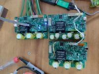
Hi all -
This is going to be my first post here - have been lurking in this thread for some time and I've decided to build one of these MESCs to test out. I think it's a pretty approachable platform to work on! I like the validated power stage layout and I think it's one of the best open source ESCs currently available. Thank you, mxlemming for the excellent open source contribution!
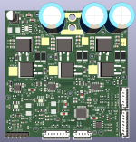
I made a couple of changes to the board layout based on the original schematic v0.5. For now, my fork will be called SQESC because my board is more or less square, to differentiate it from the main version.
This is in no way a promise that I will maintain this fork for any amount of time, but you are welcome to contact with questions etc. In my version, I decided to add the following
changes and features:
1) It seems like the STM32F303CBT6 processor used in the design has hardware
support for the CAN bus. Seeing as the USB code was recently removed from the software repository, I made the assumption this was no longer needed, and repurposed these pins for this purpose. I would like to use the CAN bus to connect multiple systems, such as BMS, taillight, display or dashboard controller/data recorder, cellular IoT module, etc in my intended application. I used the TJA1051T transceiver, which is available on JLCPCB assembly service. This is a little bit of an older transceiver, which consumes a few mA of quiescent current. As such, I added a P-Mosfet to shut the power to this chip down as needed. There are two pins on the CAN connector reserved for the termination, which is needed at the ends of the bus.
2) Some of the DC-DC converters on the board are no longer available. I
changed the architecture of the power delivery on this board. First, the high voltage input will be stepped down to 12 V using the MPS MP9486A. This chip is widely available on AliExpress for a low cost and supports 170uA quiescent current. This 12V rail is used to derive 5V and 3.3V using the TPS54331 (x2), which also has a low quiescent current and is available on LCSC.
It is possible to back-power the board with an external 12V supply on CAN connector if the MP9486A is not installed or shut down. I didn't add a diode for Diode OR redundant power in this board, or as a way to shut down the on board converter. In my application, I will not use the on board 12V converter because the driver will be co-located with the "mid-chassis" controller hub, which will implement power cut off to the board externally in order to reduce the vampire power draw, as well as secondary power cutoff should the motor controller produce an overcurrent condition.
3)
Some misc parts on the board have been replaced to better suit LCSC assembly. Due to some errors the first time ordering, some of the part selections don't match the footprints and this was manually resolved. I will try to resolve the problem in the BOM when I get some time. The three power rail LEDs are removed, as are some connectors used for presumably validation of the power layout. A "Heartbeat" LED connected to the MCU is added.
4) I
changed the location of mounting holes. They are now M2 diameter, and I will make some corresponding aluminum core PCBs for both sides of the boards, to be attached with M2 round knurled standoffs and screws/insulating washers. The aluminum PCB itself has a very good isolation layer, so without any copper layer, there will be a 1500 Vrms isolation pad built in, and thermal paste can be used to attach the plate to the back side. The aluminum PCB can have holes freely added or drilled, to make mounting easier.
5) All of the
connectors have been consolidated or rearranged into Hall, Digital IO, Analog IO, CAN Bus, Debug(2.54 header) JST PH 2.0MM connectors. The pinouts are not the same between the original and my version. The unused pin for the Hall connector is repurposed to connect a 10K
thermistor internal to the motor. I considered whether it was worth trying to design this to multiplex multiple sensors over the hall inputs, but decided that should this be needed, one sensor plus some characterization and software modelling would be a better way to estimate the internal temperature or hot spots of the motor winding.
6) The layout of the
PCB has been changed to about 87*84mm. This makes it "significantly" larger, which is acceptable in my application but might not be for yours. The purpose of this expansion is to allow for the new DC DC architecture, connectors, and CAN bus expansion. I re-routed the entire PCB with the exception of the power stage MOSFET/Power distribution layout. The layer stack up has been changed to use GND for the internal layers, with 95% of the routing on front and back. The sense resistor traces are run at 45 degree angles and/or away from the current path wherever possible. Many of the parts of the board have been spaced out more than in the original to
facilitate easier automatic JLCPCB SMT assembly.
I ordered five boards for testing. The total without gate drivers, connectors, and MP9486A comes out to about
210 USD for five assembled boards. The cost of the STM32 processor used is about 10 USD now, as opposed to 2 in the documentation. When the testing is complete, I can imagine about 2-3 boards will be surplus and available to those interested.
When the boards arrive, I will do some testing. I hope to implement some extra features in the firmware if it is feasible, such as CAN bus and variable switching frequency (Not sure if it would be possible to do this - I want the switching frequency to be changeable while the motor is turning. For example, some applications prefer the motor to produce some harmonics noise at a low speed, or the inverse - a high frequency at low current, and decreased frequency when the current is high (motor noise is greater than switching noise and efficiency is more important)
I don't currently have a way to load test this other than a 350 W geared hub motor. I might try to output a simple 60 Hz sine wave and use two large 1500VA UPS step up transformers connected in Open Delta to connect three kettles or hair driers....
If you would like to check out the changes, the repo is at https://github.com/larryqiann/MESC_FOC_ESC/tree/Change-power-supply,-add-CANBus-IC. You need to check the branch corresponding to "change power supply, add canbus IC".
I do not recommend ordering it until I can test mine and find out how many thin(?) blue wires are needed to make it work...
I do not take responsibility for any action or result taken based on the design.
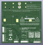
Some pictures of the layout:
