New home built controller, the first pictures

maxwell

100 W
Joined
Mar 31, 2007
Messages
157
Location
Sunny UK
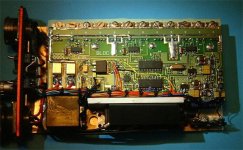
For fun I am building my own controller for any sensored BLDC motor, using the Crystalyte 408 to start with. The PCB arrived today, I want reliabilty so a home made PTH (soldered through) board was out, so I spent some money on a pro job.

I intend to implement phase advance with this, I will let you all know how it goes. For the techies, two dsPIC30F2010's do the work, one could do it all but keeping the motor algorithums seperate from the rest makes programming easier. If I was to make 1000's I would fit it all in one chip but for now...

When (oh optimist) sucessful I will publish the design here.

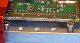
So without further ado, some pics with explanations.
 

Attachments

  • 0805s.jpg
    0805s.jpg
    27.3 KB · Views: 6,433
  • bulk-caps.jpg
    bulk-caps.jpg
    33.6 KB · Views: 6,429
  • open-half-built-pcb.jpg
    open-half-built-pcb.jpg
    44.5 KB · Views: 6,430
  • open-nopcb.jpg
    open-nopcb.jpg
    31.3 KB · Views: 6,433
  • connectors.jpg
    connectors.jpg
    21.6 KB · Views: 6,430
I'm sure you'll have a lot of interest in this! Looks like a very rugged and durable design. MIL connecters right on the box look the business 8)
 
Maxwell said:
There are 99 0805 100nF capacitors between the power rails to reduce HF losses


Very CLEVER, mister Schmart....

:D
 
Those electro's on the rear of the pcb will ultimately need vibration damping, eventually the pigtails will fracture.

Amanda
 
Some replies,

Board, circuit and board designed by me, board manufactured by TopTec

FETs IRF2907s (6) with 100V 40A shottkey diodes in //ell

Supposed to fit 100 0805 caps, bugger!

Big caps will be held by a bit of foam (I used to design Mil stuff, very aware of vibration effects)

Max volts, near 70V (the diodes and 0805s help in reducing spkes)
Max amps, I am being very conservatve with 20A per batery, 40A total, with a maximum 70A to the motor.

To limit the maximum current elegantly I am going to use the speed to calculate max PWM allowable on the fly.
 
Why the schottkey diodes?

In a BLDC bridge circuit the body diodes in the FETs will usually do the job.
 
Shottkeys are considerably faster reducing overshoot to a couple of volts and their forward voltage drop less than 1/2 of the body diode. If I was relying on the body diode I wouldn't have bothered with all those 0805s!
 
While I've never measured it, according to the datasheet on the FETs, the intrinsic turn-on time for the body diode is "limited by the inductance of the lead wires", or nearly instantaneous.

The forward voltage drop is significant.
 
In my experience of fast power electronics schottkys win out. But I do think the power saving by not dropping all those volts is also worth while.

Musn't forget the benifits of a lovely red case to house it all, it nearly matches the trike.
 
Unfortunatly I have left my programmer at work, so software will have to wait. All the various bits work.
 

Attachments

  • built.jpg
    built.jpg
    59.4 KB · Views: 6,254
IR21834s, seem nice and bullet proof, you can do a lot of damage in unconstrianed software. These have 'shoot through' prevention, FETs would get killed, even these big ones, if I turned the top and bottom on together combined with the VERY low ESR of the 9.9uF ceramic capacitor.

And my engineering brain likes the seperate common (FETs) and 0V (logic) connexions.

Other points of interest, Logic running at 3V3 and the supply to my controller 8V, both these rails derrived from the 12V FET drive voltage via linear regs. 12V supplied by an LM5007. The 350mA current source for illumination LEDs also done with an LM5007. Slow turn on done with an FET switch (saves the 'crack' of charging the caps), this is then shorted by a big (70A) relay for running.
 
Great to hear you incorporated slow turn on for the caps. I have a customer who has a 40 farad capacitor for his car stereo and I have to be really careful about reconnecting wires. That's exactly what he needs!
 
Lowell,

Add another (small) connector in //ell with a 10ohm (or so) resitor in series just for charging the caps.
 
Yeah, that's what we normally do for car audio buffs. Or charge with a battery charger first.

I can't wait to hear how your final design works out...
 
Good progress made, simple (no advance) program in the motor chip, comms to the handset, current, voltage, temperature & Ah measurements in the control chip. Bolted to my Trice (by two snazzy home made clamps) with the 37V 10Ah lithium pack attached ot the seat.

The thing works!
 

Attachments

  • new-controller-in-place.jpg
    new-controller-in-place.jpg
    64.5 KB · Views: 4,736
:shock:

Superb really nice work there, please let us all know how it goes, also do you intend to make these for sale? I would think you could sell a few!!

Super clean machine you have as well, where abouts in the UK are you? roughly? would love to see that machine of yours sometime!

Cheers

Knoxie
 
Thanks for the complements Knoxie, I do like a tidy job, half the fun is in making the thing. I think a pride in the work done helps to make it better (and a supply of free connectors helps).


It (she?) went for the first run with my controller today, a few hills and about 15mph max (no advance yet) adding in a bit of human effort I got somewhwere near 15W/h per mile. Of course there was the obligatory stop at my local for some Guinness on the way back!

The controller was 3 degrees (celcius) warmer afer the run, the motor 20, must be the low drag of the recumbent posture (re Albert and the lion).

Now for advance... (that's Sunday sorted)
 
Yes, very nice work.
I'll be very interested in seeing how the advance works out.

Post a pic of the whole bike when you get a chance. :D
 
One of the commercial BLDC chip makers (now I forget which one) implemented synchronous rectification, which would be even better than schottkey's theoretically. There was another one that had something called quasi-resonant something or other. I'll have to find that one again.

Braking is another possibility. It might work very well with a direct drive hub motor. Based on videos from the KMX guys, I guess the braking would need to be very limited to avoid skidding, but that should be doable. On a long downhill, you could still make use of it. On the other hand, it looked like skidding the rear tire could be useful if done in a controlled manner. Instant U-turns.
 
Hi all
fechter the trice like a lot of bent tadpoles uses left and right hand braking, that is left brake lever left wheel at the front is braked and the same for the right. A rear brake is avalible as an extra but is on a separate system not on the handle bars.This is what was used on the trice classic's before maxwells model started production.
this may have changed on the model maxwell has but on maxwells the only brake mount on the rear as far as I know is for a disk brake, with shimano's new hubs that have the 6 hole mounting on a separate removable "bit", this was to make it look neter when no disk brake was fitted.
I have a similar type of bent tadpole trike with the same brake setup as maxwells as well as my KMX and with care and practice U-turn brake turns are able to be done though not advised, unlike the KMX this is sold as a speed or tourer trike not a trick trike.

sorry for the lecture.
 
Understood. You probably wouldn't see me doing many power slides if I had one of those either. It looks like you could get hurt pretty easy if it flipped over, not to mention it looks really rough on the rear tire.

A rear caliper would be useful as a parking brake.
 
Back
Top