
You are using an out of date browser. It may not display this or other websites correctly.
You should upgrade or use an alternative browser.
You should upgrade or use an alternative browser.
NEW QS 165 MOTOR
- Thread starter illegalbike
- Start date
owhite
100 W
- Joined
- Aug 3, 2020
- Messages
- 285
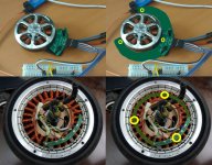
illegalbike said:Disassembly of the QS165 motor, see what's inside
HEY FOLKS! Note that you can get an english translation if you hit CC on illegalbike's great video!
illegalbike
10 W
- Joined
- Jan 28, 2021
- Messages
- 94
sensorless mode test run
battery 70V, 4443 RPM, no-load current about 3.5A
≈63kV
[img="https://illegalbike.ru/uploads/for_web/QS165_4443rpm.png"][/img]
battery 70V, 4443 RPM, no-load current about 3.5A
≈63kV
[img="https://illegalbike.ru/uploads/for_web/QS165_4443rpm.png"][/img]
illegalbike
10 W
- Joined
- Jan 28, 2021
- Messages
- 94
One of the options for the quick conversion of the QS165 motor to hall sensors.
I needed 14 5x3 mm magnets and three Honeywell SS41 sensors
The false rotor uses the same number of magnets as in the main rotor, the poles of the magnets alternate.
The angle for installing hall sensors depends on the number of pairs of poles. For 14 magnets we have 7 pairs of poles. We can choose 120° / 7p = 17.15° for this value. This is too close a distance for sensors, you can add 120°/7p + 360°/7p = 68.57°
We place the sensors above the magnets in a convenient place and prepare the files for printing
For a smart controller such as the Nucular, it will not be difficult to correct the angle of the sensors, but simple controllers will not be able to do this. I am waiting for the delivery of the oscilloscope to match the sensors to the phase. If everything goes well, I will make the rotor out of aluminum and the board out of textolite
falserotor.STL
board.STL
[img=https://illegalbike.ru/uploads/for_web/QS165_falsrotor_cheme.jpg][/img]
[img=https://illegalbike.ru/uploads/for_web/QS165_printed_falsrotor.jpeg][/img]
[youtube]CQHeNdzZCVw[/youtube]
illegalbike
10 W
- Joined
- Jan 28, 2021
- Messages
- 94
c.wagner said:Hey, very nice!
Iam currently trying to understand your calculation on hall sensor angle. Why did you choose 120° in the first place?
And why add exactly 360°?
Maybe you can point me in the right direction so I can look it up")
The circle is 360° and I want to place 3 sensors evenly on it. So there will be 120° between the sensors
We need the sensors to see all the poles at the rotor. If the rotor has only two magnets (one pair of poles), it is enough to fix the sensors through 120 ° and at every moment at least one sensor will clearly see the pole.
[img=https://illegalbike.ru/uploads/for_web/1p120g.gif][/img]
But if, for example, the rotor has 6 magnets, then it will be three pairs of poles and at the same time each sensor will see a pole. So we will not understand the position of the rotor.
[img=https://illegalbike.ru/uploads/for_web/3p120g.gif][/img]
Need to move the sensor in multiples of the number of pairs of poles, for example 120° / 3 pairs of poles, we get 40° for a rotor with 6 magnets.
[img=https://illegalbike.ru/uploads/for_web/3p40g.gif][/img]
In my case, the rotor has 14 magnets, which means there are 7 pairs of poles in it. I just divide 120° by 7 pairs of poles and get an angle of about 17.14° between the sensors
But it's too close for a small rotor and the sensors won't fit
[img=https://illegalbike.ru/uploads/for_web/falsrotornogood.png ][/img]
Since physical phenomena are repeated on the entire circle, we can add a step of 360° / 7 pairs of poles to this angle. That is, every 51.43° everything repeats, just add it to our angle of 17.14° and get 68.57°
It's convenient for me
[img=https://illegalbike.ru/uploads/for_web/falsrotorgood.png ][/img]
PS: if desired, you can add a step of 51.43° again and get 120°. For 7 pairs of poles, the physical 120° can be used if it is convenient
illegalbike
10 W
- Joined
- Jan 28, 2021
- Messages
- 94
in order for any simple controller to work with homemade board
for hall sensors, you need to coordinate them with the back EMF of the motor
I tried to revive an ancient oscilloscope from the USSR, but it seems time killed it.
[img=https://illegalbike.ru/uploads/for_web/oldoscil.JPG][/img]
A new oscilloscope was delivered today, I'm holding it in my hands for the first time, it seems nothing complicated
[img=https://illegalbike.ru/uploads/for_web/testoscil.JPG][/img]
larsb
1 MW
illegalbike said:But if, for example, the rotor has 6 magnets, then it will be three pairs of poles and at the same time each sensor will see a pole. So we will not understand the position of the rotor.
I’ve seen some calculations of the hall sensor angles before, from my mind the 120 deg position of the halls works for all the magnet counts except the variations of 6 magnets you show here. I think it’s easier for most people to just use this instead of a split angle like 17.14
illegalbike
10 W
- Joined
- Jan 28, 2021
- Messages
- 94
larsb said:I’ve seen some calculations of the hall sensor angles before, from my mind the 120 deg position of the halls works for all the magnet counts except the variations of 6 magnets you show here.
the same problem if the number of poles is a multiple of three
3, 6, 9, 12...
larsb said:I think it’s easier for most people to just use this instead of a split angle like 17.14
I think that knowledge of physics gives an advantage.
rarely will it be convenient to place sensors from different sides of the motor at 120°, a compact solution looks better, right?
Attachments
Elektrosherpa
1 kW
- Joined
- Feb 7, 2021
- Messages
- 386
illegalbike said:c.wagner said:Hey, very nice!
Iam currently trying to understand your calculation on hall sensor angle. Why did you choose 120° in the first place?
And why add exactly 360°?
Maybe you can point me in the right direction so I can look it up
The circle is 360° and I want to place 3 sensors evenly on it. So there will be 120° between the sensors
We need the sensors to see all the poles at the rotor. If the rotor has only two magnets (one pair of poles), it is enough to fix the sensors through 120 ° and at every moment at least one sensor will clearly see the pole.
[img=https://illegalbike.ru/uploads/for_web/1p120g.gif][/img]
But if, for example, the rotor has 6 magnets, then it will be three pairs of poles and at the same time each sensor will see a pole. So we will not understand the position of the rotor.
[img=https://illegalbike.ru/uploads/for_web/3p120g.gif][/img]
Need to move the sensor in multiples of the number of pairs of poles, for example 120° / 3 pairs of poles, we get 40° for a rotor with 6 magnets.
[img=https://illegalbike.ru/uploads/for_web/3p40g.gif][/img]
In my case, the rotor has 14 magnets, which means there are 7 pairs of poles in it. I just divide 120° by 7 pairs of poles and get an angle of about 17.14° between the sensors
But it's too close for a small rotor and the sensors won't fit
[img=https://illegalbike.ru/uploads/for_web/falsrotornogood.png ][/img]
Since physical phenomena are repeated on the entire circle, we can add a step of 360° / 7 pairs of poles to this angle. That is, every 51.43° everything repeats, just add it to our angle of 17.14° and get 68.57°
It's convenient for me
[img=https://illegalbike.ru/uploads/for_web/falsrotorgood.png ][/img]
PS: if desired, you can add a step of 51.43° again and get 120°. For 7 pairs of poles, the physical 120° can be used if it is convenient
That was a perfect explanation
larsb
1 MW
illegalbike said:larsb said:I’ve seen some calculations of the hall sensor angles before, from my mind the 120 deg position of the halls works for all the magnet counts except the variations of 6 magnets you show here.
the same problem if the number of poles is a multiple of three
3, 6, 9, 12...
larsb said:I think it’s easier for most people to just use this instead of a split angle like 17.14
I think that knowledge of physics gives an advantage.
rarely will it be convenient to place sensors from different sides of the motor at 120°, a compact solution looks better, right?
Poles will always be pairs so there’s never a 3 or a 9,
12 can be divided by 6, no 15, 18 divides by 6 etc. I agree that 120deg takes more space but it has the advantage of being (almost) foolproof.
larsb
1 MW
bymannan said:What adventure does the encoder has over hall sensor?
Encoders are far more accurate than hall sensors
Halls update position only every 60 electrical degrees
(Electric degrees = Physical degrees * pole pairs)
illegalbike
10 W
- Joined
- Jan 28, 2021
- Messages
- 94
larsb said:Poles will always be pairs so there’s never a 3 or a 9,
12 can be divided by 6, no 15, 18 divides by 6 etc. I agree that 120deg takes more space but it has the advantage of being (almost) foolproof.
I'm talking about pairs of poles. 3 pairs = 6 magnets, 9 pairs = 18 magnets
larsb
1 MW
Ok, understood.
It’s a common source of confusion; ”magnet poles” really means the number of poles, north and south whereas ”pole pairs” are the number of north and south pairs so it’s better to say pole pairs when meaning just that.
It’s a common source of confusion; ”magnet poles” really means the number of poles, north and south whereas ”pole pairs” are the number of north and south pairs so it’s better to say pole pairs when meaning just that.
owhite
100 W
- Joined
- Aug 3, 2020
- Messages
- 285
larsb said:Encoders are far more accurate than hall sensors
This is probably known by all concerned but I believe illegalbike's interest in going with halls is that they are compatible with his controller.
I still wonder if there might be a "simple" solution to translating the output of the encoder to a signal that would be compatible with a controller that uses hall signals with a microcontroller. The microcontroller would also make it possible to handle the angle correction that Illegal mention here. Of course this is a bit more theoretical rather than practical -- it would take some comparison/performance testing that would be much easier with a motor that had both halls and encoders.
This is a thread [link] where someone has done this.
illegalbike
10 W
- Joined
- Jan 28, 2021
- Messages
- 94
owhite said:This is probably known by all concerned but I believe illegalbike's interest in going with halls is that they are compatible with his controller.
Yes
owhite said:I still wonder if there might be a "simple" solution to translating the output of the encoder to a signal that would be compatible with a controller that uses hall signals with a microcontroller.
Roman (@YTW200) from Russia made boards converting data from a standard central magnet for the encoder into signals simulating hall sensors. I'll test them when they arrive
[img=https://illegalbike.ru/uploads/for_web/encoder-to-hall.jpg][/img]
larsb
1 MW
That’s a nice development! It is the same way the rls rmc22 encoder works, i’ve used that for some 10000kms and it works beautifully as replacement option for hall sensors.
owhite
100 W
- Joined
- Aug 3, 2020
- Messages
- 285
rider119 said:Does anyone have a CAD model of this motor?
I have one that I created from the drawings -- and mine has arrived so I can confirm if it is accurate. What file format would you like?
owhite said:rider119 said:Does anyone have a CAD model of this motor?
I have one that I created from the drawings -- and mine has arrived so I can confirm if it is accurate. What file format would you like?
sldprt or step would be great! Thanks
owhite
100 W
- Joined
- Aug 3, 2020
- Messages
- 285
rider119 said:sldprt or step would be great! Thanks
Here is a step file for the QS165: see this link
Items to note: This was generated with a combination of using the diagram supplied by QS link and taking measurements from the motor itself. I did not focus on accuracy of details like fins. The focus was mostly on what was needed to mount the motor, width of housing, placement of M8 bolt holes, pulley diameter and width should be within +/- 1mm.
It would be helpful if someone can confirm they can download and view in their CAD.

owhite said:It would be helpful if someone can confirm they can download and view in their CAD.
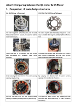
it works. I used to make a quick comparison with the QS 138 model.
QS claims torque specs very close between the two (47Nm vs 55Nm peak) even though they have 35H vs 75H magnets heights. A bit concerned the capacity of the QS 165 to deliver such torque without overheating (as the Surron motor does).
They do not advertise the continous torque spec for the QS 165.


illegalbike
10 W
- Joined
- Jan 28, 2021
- Messages
- 94
QS165 on hall sensors is ready!
I recorded a short video on adjusting the angle of the sensors. English subtitles will be coming soon, enjoy watching
[youtube]fyn6x71TRUk[/youtube]
I recorded a short video on adjusting the angle of the sensors. English subtitles will be coming soon, enjoy watching
[youtube]fyn6x71TRUk[/youtube]
Similar threads
- Replies
- 1,668
- Views
- 429,934
- Replies
- 11
- Views
- 8,837