confusedinkc
1 µW
- Joined
- Jul 27, 2018
- Messages
- 2
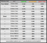
Hey guys, I'd like to learn how to build a battery pack. I have read several threads on here regarding the current rating for nickel strips. There seems to be a consensus among the experienced pack builders and the resident experts that a 7mm/.15mm strip is good for 5 amps (or 7 at the most).
I generally like to verify data presented from charts or formulas to make sure they match up with my reality. Seeing is believing, right?
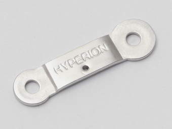
I obtained a sample of some common welding strips for testing. The part that goes between parallel banks is 7mm in width, thickness is .15mm. I wanted to determine the current capability of this small section of strip (about 20mm).
I connected the strip in series with a 60V supply and a load that draws 10A. There was a question in my mind regarding the proper test voltage, either the differential voltage between cells (4V) or full pack voltage, so I opted for the worst case just to make sure. The supply has it's own volt and current meter, and I put an additional meter right at the strip for verification. Please refer to the pics.
The result was that the strip remained stone cold, no heat at all, none.
I measured 0.018 V across the strip. So the resistance is:
.018V/10A = 0.0018 ohms. According to my math (somebody please check it), the power dissapation is .018V * 10A = 0.18W.
Granted that is not nothing, but seems negligible. Strange, huh? What's going on? All the related posts in this forum says that strip is only good for 5-7 amps! I held the strip in my fingers for several minutes, no heat at all. I'm not getting any correlation, not even close.
Did I do something wrong? What am I missing? Is it just my alternate reality? Can some technician or engineer verify my results please?
Note: I posted this request several days ago at the end of an old thread, that is probably dead, so got no response (moderator, please delete the other post if that's an issue). Hopefully someone will see it now and respond. Can anyone explain the discrepancy?
Thanks a lot guys.
Signed,
Confused in K.C.

View attachment 5
View attachment 4
.jpg")
.jpg")
.jpg")
I generally like to verify data presented from charts or formulas to make sure they match up with my reality. Seeing is believing, right?
I obtained a sample of some common welding strips for testing. The part that goes between parallel banks is 7mm in width, thickness is .15mm. I wanted to determine the current capability of this small section of strip (about 20mm).
I connected the strip in series with a 60V supply and a load that draws 10A. There was a question in my mind regarding the proper test voltage, either the differential voltage between cells (4V) or full pack voltage, so I opted for the worst case just to make sure. The supply has it's own volt and current meter, and I put an additional meter right at the strip for verification. Please refer to the pics.
The result was that the strip remained stone cold, no heat at all, none.
I measured 0.018 V across the strip. So the resistance is:
.018V/10A = 0.0018 ohms. According to my math (somebody please check it), the power dissapation is .018V * 10A = 0.18W.
Granted that is not nothing, but seems negligible. Strange, huh? What's going on? All the related posts in this forum says that strip is only good for 5-7 amps! I held the strip in my fingers for several minutes, no heat at all. I'm not getting any correlation, not even close.
Did I do something wrong? What am I missing? Is it just my alternate reality? Can some technician or engineer verify my results please?
Note: I posted this request several days ago at the end of an old thread, that is probably dead, so got no response (moderator, please delete the other post if that's an issue). Hopefully someone will see it now and respond. Can anyone explain the discrepancy?
Thanks a lot guys.
Signed,
Confused in K.C.
View attachment 5
View attachment 4
")