Hello everyone  . I have an issue with my ebike and would be really happy if someone with more experience could help me.
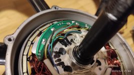
When I connect my hall sensors to controller, suddenly the voltage (from controller) drops from 5V to around 0,8V all around the circuit. I have already replaced my controller and the issue persists. 48V power is OK, it's only 5V that causes problems.
If there is someone who could give me some guidance on what could that be, I would be very thankful?
. I have an issue with my ebike and would be really happy if someone with more experience could help me.When I connect my hall sensors to controller, suddenly the voltage (from controller) drops from 5V to around 0,8V all around the circuit. I have already replaced my controller and the issue persists. 48V power is OK, it's only 5V that causes problems.
If there is someone who could give me some guidance on what could that be, I would be very thankful?