One KiloWatt 18S Bulk Charger

dnmun said:
i have the transistors if you wanna replace them, and the base resistors too usually blow. you have to replace them in matched pairs.

Is that the most likely failure? It is a 400W model set for 75V 4A so should not run very hot. It was a warm evening so garage might have been warmer than usual, but didn't start charging until after dark.

I am willing to give it a shot. Thanks for any info.
 
Alan B said:
The power density (watts per cubic inch) is highest with the 240 watt model, and the price is lower per watt and with fewer watts there is quite a cost reduction.

exactly because of this i recently purchased two of them for a travel charger build. i will also use a display, but with additional timer cut off function.
Alan, do you bulk charge the complete 18s or do you split them up to 6s like before?
 
Alan B said:
I haven't deployed the 240W models yet. Probably will do the 6S per supply for now. We'll see how it goes.

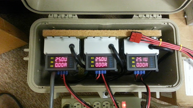
I'm taking a fresh look at this bulk charging setup. At the moment the size and weight of these robust power supplies doesn't lend itself to installing on my CroBorg, I would rather add a few batteries instead. But I would like to have a single plug and auto-shutoff charging with some protection and safety monitoring at home and work. I may make a prototype with the 240W units since I have another working charger at the moment. Some of the design elements I'm thinking about now:

- safety grounded ebike frame (so at least 3 conductors required)
- ground isolated (uses one or more of the LED regulated supplies with adjustable voltage and current limits)
- single plug to charge (below handlebars due to available wire access)
- auto start and auto termination (plug and go, no buttons, switches, etc needed)
- removes AC power from the supplies at end of charge (solid state relay)
- use separate control power (USB wall wart)
- voltage and current sensing
- monitors voltage and current for start and end of charge plus protection and safety
- voltage, current, integrated current and time displays (LCD)
- charge time limit cutoff and integrated charge cutoff protections (amp hours)
- setup to handle 12S (50V) and 18S (75V) with one charger
- charge current 10A or 13A depending on supplies used (3 each 24V 240W or 320W HLG)
- GFCI in power cord (not essential but not hard to do)
- house in Pelican 1430 case
- delayed charging timer (requires knob/button...)(maybe)

I'm still tweaking the design, trying to keep it simple and still do the essential things. The nonessential functions must be software, if they require much extra hardware I'll probably drop them.

Concerns

- inrush current when plugging in bike to unpowered supplies - is this a problem?
 
if you can turn off the battery at the BMS then it will not spark when you connect to the unpowered charger. you can use a precharge resistor to fill up the output caps so it doesn't spark if you don't use a BMS.
 
dnmun said:
if you can turn off the battery at the BMS then it will not spark when you connect to the unpowered charger. you can use a precharge resistor to fill up the output caps so it doesn't spark if you don't use a BMS.

I've been thinking about various ways of precharging, but this is tricky to do without adding parts. If you add resistance to the path, then you need a relay or FET to bypass it, or know when to turn on the power supplies to precharge. But if there is no action other than plugging in the DC plug it limits how you know when to precharge. I suppose an FET current limiter would work, but again that is adding a few parts, and some loss.
 
Alan B said:
The more look at this the less I like series connecting three supplies. When they are off the voltage feedback from the battery could present up to 75V on one supply if things don't divide evenly. It is messy to fix that.

aren't for this diodes needed across the output of each supply? That would not be that messy to fix.
It is written in the manual from meanwell itselfe and many other manufacturer do recommend the same when connecting their supplies in series.
 
The diode is part of the answer, but it doesn't solve the reverse power from battery dividing unevenly when the supplies are off and overvolting the output capacitors case. Meanwell doesn't publish an output breakdown voltage rating which should not be exceeded when series connecting supplies. It is unlikely that the output stage has been designed to handle triple the output voltage. Using Zener or TVS diodes is one way to possibly deal with this problem. Another solution is to do as I have been doing and not connect the supplies in series.

I haven't found Meanwell recommendations on series connecting LED supplies. I did find one recommendation from Meanwell AGAINST connecting LED supplies in parallel.
 
KW 18S Charger Upgrade

Made a small upgrade to the existing KW 18S charger this weekend. Added more metering so all three sections get meters. The right hand meter's calibration is slightly off, the voltages are not perfect, but they're closer than the readouts indicate.

The output wires from the meters were upgraded, longer lengths of 12 gauge red/black were used and crimp connectors used to the back of the meters. This should reduce the heating experienced in the old crimped connections covered in heatshrink. Update- the heating that occurred in the crimped butt connectors covered with heatshrink is gone, the supplies get warm but not hot, the wires and connectors run cool.

Also ganged the three output connectors into one 2x3 block for more convenient plug-in. Automatically controls for charging and shutoff are being looked at for a future upgrade.

20141020_112357.jpg


More on the 240 Watt LED Supplies

I also compared the 240 to the 320 watt LED supplies. The 240's seem a lot smaller and lighter, though they are both rather large and heavy for onboard charging on a bicycle:

20141019_120120.jpg
 
I've just received two Meanwell HLG-240-48A supplies (£58 for both inc deliv) and although I don't have any 320w supplies to compare with, they are larger and heavier than I was expecting. However that are much smaller (and hopefully more reliable) than the EMC-1000 alloy charger that they will be replacing for 'on the road' charging.
 
danielrlee said:
I've just received two Meanwell HLG-240-48A supplies (£58 for both inc deliv) and although I don't have any 320w supplies to compare with, they are larger and heavier than I was expecting. However that are much smaller (and hopefully more reliable) than the EMC-1000 alloy charger that they will be replacing for 'on the road' charging.

Where did you get them? Thanks! :)
 
riba2233 said:
danielrlee said:
I've just received two Meanwell HLG-240-48A supplies (£58 for both inc deliv) and although I don't have any 320w supplies to compare with, they are larger and heavier than I was expecting. However that are much smaller (and hopefully more reliable) than the EMC-1000 alloy charger that they will be replacing for 'on the road' charging.

Where did you get them? Thanks! :)

I purchased them from ebay, although they were the last two from the seller. Might be worth asking if they'll be getting any more in:

http://www.ebay.co.uk/itm/171480244199
 
You can put them in series if you have diodes across them, and I have a diode to stop backfeeding the battery into the supplies (and draining it, due to the voltage dividers for the reference section of the power supply).

I have 4 X 36V supplies in series charging a Vectrix, total voltage is 155.2 - been doing this for a few months, every day, usually putting in 2-3Kwh at a time (slowly).
 
Connecting Power Supplies in Series

http://www.acopian.com/acopianPowerSupplies/entry.aspx?nsId=17

Acopian has three requirements for connecting supplies in series (to a standard load):

1) The combined output voltage should not exceed the output breakdown voltage

2) Install a reverse biased diode across each supply with PIV exceeding the total voltage

3) The current rating of each supply must exceed the maximum current required by the load

They are assuming regular loads, not batteries. The batteries put voltage back into the power supplies which a normal load doesn't tend to do. Here's the rub: Each supply has an output capacitor (typically) with a voltage rating. What's that voltage rating? If the AC goes off, and the voltage coming back from the battery divides unevenly across the supplies then one supply could get nearly the total system voltage, and this may exceed the voltage rating of the output capacitor, which is unlikely to be 2 or 3 times the rated output voltage. The voltage division depends on leakage currents which may not be well controlled from one supply to another.

I don't care much for this approach since you are depending on things that aren't specified about the power supplies, and may not be controlled. When the supplies are not powered (as when there is an AC failure, or when the supplies are unplugged, etc) the diode prevents reverse bias but it doesn't prevent uneven division of the battery voltage.

It is so easy to charge a separate section of the battery with each supply in many cases, and this avoids the diode and the other problems. Set all supplies for the same voltage and current and charge until the resulting current is less than 3% of capacity.
 
Thanks Alan for the detailed explaination. Now i understand.

i have seen a shematic with one diode parallel and one in series at each supply. would this help?
 
Series Diodes

A diode in series blocks the reverse current when the supplies are off. Only one is needed, not one per supply.

A diode in series also causes a voltage drop that is dependent on current and at 12 amps it will dissipate about 12 watts and get very hot. It is a voltage drop that changes with current and wastes energy.

Auto Shutoff Plan

I'm collecting parts for the next upgrade of my chargers. I'll do it to the 240W * 3 version first (which is not built up yet), then to the 320W * 3. The goal is to shut off each charging power supply when it is done charging. This will be detected by measuring the three charging currents, one for each supply. The current measurement will be done using a hall sensor so the measurement is isolated and the controller will measure a small DC voltage from the sensor. The supplies will be controlled using a separate solid state relay on the AC side, so 3 SSR's will be needed.

The controller will be a Teensy 2.0 with an LCD display. It will have three voltages to read from the current sensors, and three SSR's to control by sending a 0V or 5V signal, plus the display to drive. The Teensy will be powered by a small USB type wall transformer. Everything will mount on a 1/8" aluminum plate which will slide into the Pelican 4310 case. The aluminum plate will be grounded and will dissipate the heat from the SSR's and LED Supplies. The AC side will have a circuit breaker and a removable AC cord with 3 wires including ground.

The software will start by measuring the voltage offset of the hall sensors, then turn on the AC to the supplies via the SSRs to reduce sparking and display a "ready" message. When the bike battery is connected it will display current and integrated amp-hours for each of the three sections. It will shut each section off when the current drops below a threshold of 0.2A which is 1% of pack capacity. The Pololu sensor PCB I'm looking at has 167mV per amp of output signal so the trip point will be about 33mV from the zero offset. The Teensy ADCs will have a bit resolution of 5/1024 or about 5mV. So the trip off point will be about 6 counts, and significant averaging will be used to make a clean signal. The cutoff point could be raised, 3% is a more often recommended cutoff.

I'll put a few other safeguards into the software such as maximum charging time and maximum amp hours.
 
Charger Controls Upgrade

Ordered most of the parts and have some already:

teensy board and WW pins have
display have some
aluminum 1' by 1' by 1/8" have
pelican case ordered
solid state relays ordered
power inlet jack ordered
circuit breaker ordered
power supplies have
usb power supply and cable have
wirewrap wire and tools have
hall effect current sensors ordered
wire wrap wire and tools have

I'm going to plan for adding voltage readouts later, but not do that at the start. The current readout is necessary, the voltage readouts are a nice improvement.

differential amplifiers selected
 
Here's a block diagram for the updated charger:

chgcont2014.png


Many parts have arrived, still waiting on a few. The box is critical for sizing the aluminum and starting parts layout, so not much can happen before that arrives. I ordered the case awhile back but they sent the wrong item and that is taking awhile to straighten out.
 
i'm excited to see your electronic finished and how it works. wish you success.

might there be a chance to also use it with 2 or more supplies connected in series?
i think the relais must be swapped to the charging lead and it has to be programmed to open the connection to the battery before AC power is turned off.
 
sorry for my writing style. i meant if the supplies are connected in series (like i plan to do), the relais should be installed in the charging lead instead of the AC wire to prevent the them from unevenly divided reverse power. right?
 
Back
Top