One KiloWatt 18S Bulk Charger

Alan B said:
We cannot depend on software to protect against unevenly divided reverse voltage. Hardware must be used to do that.

as mentioned i already have two HLG-240 48V and want to build also a charger with display and cut off funcion, but the difference is i do not charge my battery split into several groups like you do. because of this i have to install the cut off relay between supplies and battery because it MUST open this connection before AC power is turned off - otherwise the back voltage from the battery could be unevenly devided and the output capacitors could be damaged. i am right?
for example when someone unplug AC power or if there is a blackout -> the relais must cut instant connection. this is where im not sure how i can achieve this.. maybe you have an easy doable suggestion for me :)

much thanks for your help
 
Alan B said:
What is so hard about adding one wire into your battery pack to the midpoint for charging?

i charge through my Adaptto controller to have accurate s.o.c. readings even when i charge not to full. also i do not want to change the nice Neutrik 2pole connector system.
 
Any update on this build?
 
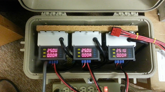
Still using it most every day, this is the 18S 1kW version. The 700 watt version is in a project box waiting for some time to work on it. Other projects are getting priority at the moment.

20141020_112357.jpg
 
Alan B said:
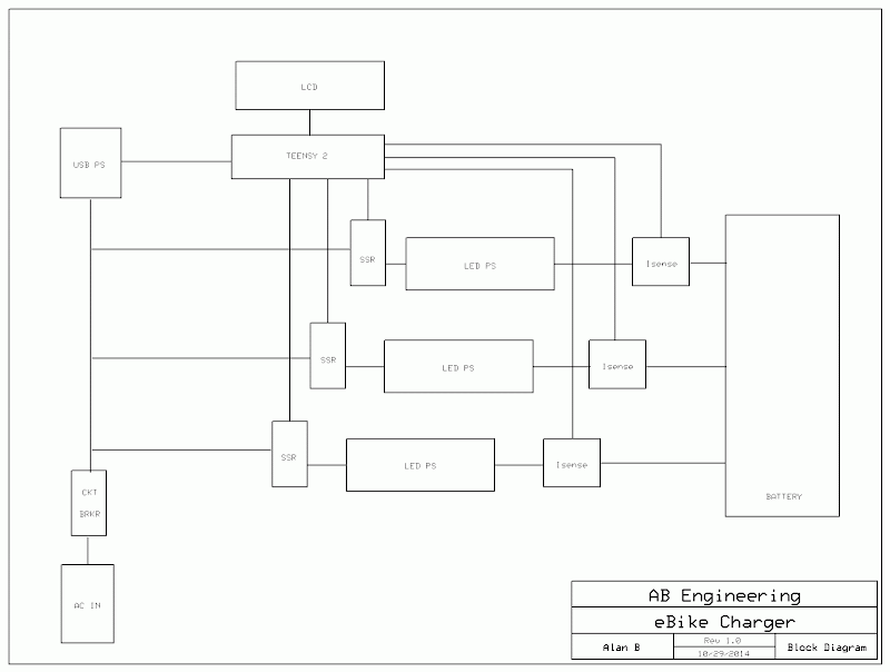
Here's a block diagram for the updated charger:

chgcont2014.png


Many parts have arrived, still waiting on a few. The box is critical for sizing the aluminum and starting parts layout, so not much can happen before that arrives. I ordered the case awhile back but they sent the wrong item and that is taking awhile to straighten out.

SO this is the automated charger you built?
Or are you just using the HLG and the Ah meters and switching off manually?
 
A few months ago I upgraded the 18S CroBorg battery from 20AH Turnigy 25C lipo to 32AH MultiStars, and this charger is handling the new pack with the same solid reliability. The current drops down to 60-70mA after a few hours (just like it did with the 20AH pack), then I unplug it. It charges silently which is important since it is in a building, and the UL listings are required for it to be used there. The displays show the state of the charging at all times, and I periodically check the per cell voltages with a battery medic display. Since I'm charging to about 4.16V/cell there is a fair amount of room for imbalance and still remain under 4.2V, and these MultiStars are extremely well balanced right out of the box. The balance connectors are under the hood now, and the charge port is under the seat, so that cleaned up the wires near the crank. The single 6 conductor plug makes connection easy and quite positive, it holds much more positively than a single 2 conductor PowerPole does. I have a 6 conductor to 2 conductor adapter on the bike for connecting to the BmsBattery Alloy charger for 2 amp slow bulk charging. For the occasional balancing charge (only once so far on this pack) I use a BC168 "through the balance leads" charger at 2 amps (and plug it in three times).

I stopped working on the auto-shutoff circuitry for the moment due to more pressing projects, but I would still like to do that. It just isn't required now since I'm right nearby, and these LED supplies insure the voltage is safe. A simple timer would handle this termination quite nicely if you know the integrated charge that was used (such as the Cycle Analyst reads out). The technique I plan to use is to monitor the charging current and disconnect AC power to the LED supply when the charging current drops below 100mA.
 
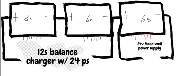
Hello, I have a 18s that I would like to charge as one, at the same time, without disconnecting the series connection. Would the below work? I tried searching but I keeping hearing something at a 'common ground' being a problem?


Screen Shot 2020-04-14 at 22.52.28.png
 
Hmm, bummer. Many thanks, I'm not 100% sure, maybe I won't then. But I can still do one at a time without unplugging? Like the 12s section, then the 6s. The 12s charger is a EvPeak A9 Rc Battery Charger & Sky-RC 380 power Supply. It says it has short protection. So the safest way in this config would be to buy 2 more mean well supplies and put in series them?
 
Yes, you can do one section at a time as long as the bike system is not grounded.

This thread is about three meanwells effectively in series. Works fine, as these particular meanwells are suited for battery charging. Not all Meanwells are. They need to have floating grounds and be current and voltage limited. The LED supplies used here are.
 
Ok thanks. I charge the batteries off the bikes. I bought one similar to the OP, but no 'A'. Not adjustable. I reread the post, so I understand that I don't need to series them. I can make 3 charge ports wired similar to my drawing but in 3 section. The AC input can be parallel into 1 plug?? I see they also do a HLG-320H-24B. It comes with 2 outputs. Would they be able to charge 2 6s?
 
Alan B said:
Yes, you can do one section at a time as long as the bike system is not grounded.

This thread is about three meanwells effectively in series. Works fine, as these particular meanwells are suited for battery charging. Not all Meanwells are. They need to have floating grounds and be current and voltage limited. The LED supplies used here are.
By "floating ground", is that the equivalent of electrically isolated, both between source AC and output DC sides, therefore as well as between each others' outputs?

Can't the three output pairs from each PSU thus be serially connected together, and the nominal 72V output through the "final" pair of leads, applied to bulk charge an 18S battery?


Audisport09 said:
Ok thanks. I charge the batteries off the bikes. I bought one similar to the OP, but no 'A'. Not adjustable. I reread the post, so I understand that I don't need to series them. I can make 3 charge ports wired similar to my drawing but in 3 section. The AC input can be parallel into 1 plug?? I see they also do a HLG-320H-24B. It comes with 2 outputs. Would they be able to charge 2 6s?
Yes but, if the two outputs are not isolated from each other, just in parallel, then the two 6S must not be wired in series together while doing so.

Alan please correct if this is not worded precisely correct.
 
Folks, there are a number of ways to do this, and the differences are subtle but can be important.

Redundant connections can cause unwanted currents to flow and unwanted voltage drops or even short circuits.

Either use independent floating supplies or supply outputs and allow the series connections to be internal to the pack (6 wire connection the way it was done here), or perform the series connection externally and connect only two wires to the pack. The supplies should be protected against voltage coming back in the output terminals, as well as against excessive current that charging batteries can demand. You have to consider the wiring and the various situations that can occur. If you have separate power cords then the partially powered combinations must be provided for. Keeping the outputs separate simplifies the situation somewhat. Each will either see 6S DC or not, but they should not see greater voltages on their outputs. Connecting supplies externally in series gets into other issues to protect those supplies against various situations including higher DC voltages coming in their output leads. That's beyond the scope of this discussion, I did not do that or test that.

The supply voltages and current limits need to be adjusted to the pack's requirements, in my case I used 25.0V per 6S section. 24V would be undercharging the pack at 4.0V per cell. Which is ok if that's what you want to do. But non adjustable supplies are likely to be at different voltages and I want to use matched voltages on my pack. If the current limits are different then the pack will go out of balance during charging until charging is compete. If charging is halted for some reason the 6S sections may be in different charge states. This could lead to a 6S section running out of juice before the others during discharge. Since per cell group LVC is not being monitored you never want to hit LVC with the pack. In my case when the pack got low I got off and pushed rather than risk damaging the pack. You are the BMS.

Some means of balancing the pack should be provided. I do that periodically by using a 6S balance charger and connecting it 3 times. This is done about every 6 months or year. In between the balance is manually checked with a 6S meter periodically.

I do occasionally charge the pack with a 2 wire charger. This works fine as well. In that case I use a supply that is designed to charge 18S voltages directly like the high voltage Satiator.
 
Perhaps it is elsewhere I've read, identical HLGs can be stacked in parallel or series'd without a problem.
 
I've heard similar things, however there are no specs or application notes for this that I'm aware of. So we don't know what the actual limits are. Too many in series will exceed the voltage limits of some components at some point. It would be ideal to find a Meanwell app note that would contain the details of how to do this and remain within the design specs of the supplies.

For parallel they should be set to the same voltage. If not the higher voltage power supply will carry more of the load.

In series the lower current limit setting will determine the current limit.
 
Alan B said:
It would be ideal to find a Meanwell app note that would contain the details of how to do this and remain within the design specs of the supplies.
Unfortunately I've never seen anything like that. Just anecdotal experience of those using some of them in parallel or series or both (including myself), with success so far. But i don't have direct experience with using more than two in series.

The Meanwell site itself has these two technotes, plus some FAQs, which aren't really what you're after, but do discuss some of the aspects of it, and either warn against it or show alternatives:
tech notes link https://www.meanwell.com/news.aspx?c=5
Applications on Redundancy Function of LED Display Power Supply
https://www.meanwell.com/newsInfo.aspx?c=5&i=855
(complete article not quoted, just the diagrams, rest is at above link)
Fig.2 Redundancy System of Diode in Series
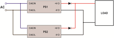
20200324_045901fig_2.png
Fig.3 LSP-160 Redundancy and Parallel Connection
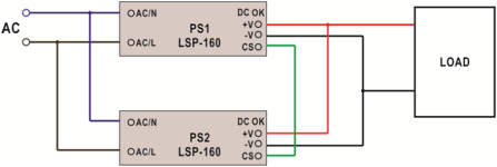
20200324_050004fig_3.png


Redundant function and Application of Power Supply
https://www.meanwell.com/newsInfo.aspx?c=5&i=847

then some FAQs
Can LED power supplies be connected in parallel?

MW LED power supply does not have parallel “current sharing” function so it is not suitable for parallel connection. For high power requirement, please select higher wattage power supply or divide LED load into smaller subsections to be powered by individual power supplies. Example of such LED configuration can be found in figure 5. As shown in fig. 5, the connection between -V of the LPC-35 units should be severed and not connected in common. On the contrary, small wattage LED loads can be connected in parallel and be powered by a single high wattage power supply. But, the ability to divide current evenly must be taken into consideration.
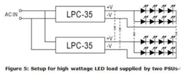
20180706_050708B4E.png

https://www.meanwell.com/qa.aspx
How to choose a suitable power supply for a charging application?

MEAN WELL has launched ENC, HEP-600C, GC, PA, PB, RPB and RCB series for battery charge applications (30~360W). However, if these models still cannot fulfill customer’s requirements, there is an alternative for the purpose. Power supplies with constant current limiting as overload protection are suggested. Charge current varies in battery percentage (full or flat), there is high possibility to trigger overload protection when battery is low, those with overload protection as hiccup or shutdown will stop charging the battery in low battery condition. Yet, using a power supply as charging purpose is considered as over load usage, modification is required. Please contact MEAN WELL for the request.


Can we use LED CC model as a charger?

MW has several charger products, and we suggest choosing them first. Chargers would be more suitable since they are designed for charging applications. Safety & Approvals should be taken into account. If you really cannot find a proper model in our chargers series, our LED CC models can be used as charger. Please choose suitable products after confirming the current and voltage specification on the datasheet of the battery.

Can I use MW LED drivers at full load continuously? Most of the AC/DC power supply are suggested to use at 70% load.

LED Drivers are recommended operate at full load as long as it observes the working temperature specified in the datasheet, which means Tc measurement results should be equal to or less than the stated Tc in the datasheet. 5 years warranty complies as long as drivers operate within working Temp and Tc. Limit as well.


not related, but of interest:
In MEAN WELL's catalog, we see AC and DC at input, what is it all about?

Due to different circuit designs, MEAN WELL power supply's input consists of three types as below:
(VAC≒VDC)
a.85~264VAC;120~370VDC
b.176~264VAC;250~370VDC
c.85~132VAC/176~264VAC by Switch; 250~370VDC

In a and b inputs models, power supply can work properly no matter under AC or DC input. Some models need correct connection of input poles, positive pole connects to AC/L; negative pole connects to AC/N. Others may require opposite connection, positive pole to AC/N; negative pole to AC/L. If customers make a wrong connection, the power supply will not be broken. You can just reverse the input poles and power supply will still work.
In c input models, please make sure that you switch the 115/230V input correctly. If the switch is on the 115V side and the real input is 230V, the power supply will be damaged.


Why is that during LED power supply operation the LED sometimes varies in brightness or flickers?

MW developed many power supplies series specifically for LED application. Single stage PFC was used in such developments due to low cost. This topology has the following restrictions:

AC fluctuation
This topology does not use input bulk capacitor. For this reason, in areas with low AC quality, output voltage and current may become unstable causing variation in LED brightness. If the input AC voltage is stable then this problem will not occur.
Output ripple
This is also caused by lack of input bulk capacitor. As compared to power supplies using dual stage PFC, the ripple will be significantly larger (see Figure 4). There could be instances where the low end of the ripple may be too low for the driver IC to operate properly and the LEDs will start to flicker. To solve this type of problem, the output voltage can be adjusted higher so the low end is higher than the driver’s minimum working voltage. Or simply select a PSU with higher rated voltage.
Current harmouics
Single stage PFC power supplies are optimize for constant current drive. Using these supplies as constant voltage sources (such as application including cascading a constant current driver IC), the harmonics might be worsen in this case. When operating in areas with unstable utility voltage or with driver IC, we highly recommend using general application types as found in table 1. Avoid using single stage PFC if possible, or contact MEANWELL.
 
Awesome, last question please I promise lol. If I replace the Sky-RC power supply with a Mean Well HLG-600H-24A to power the EvPeak a9 balance charger. Would that eliminate any possible grounding issues, so that I could do my original plan of charging 12s and 6s at the same time? Or is the Ev peak a9 still any issue?
 
Back
Top