One KiloWatt 18S Bulk Charger

deVries said:
Anyway, I'm just trying to come-up with a better reason or charging scenario to use the Dimmer feature to drop the current to less than 1A vs just turning off the AC side???
Alan B said:
When a cell hits HVC the charge needs to be terminated unless there is a current diversion for balancing.
Yep - the 'dimming input' does not appear to offer anything useful in this situation. Got to let that idea go as a bad plan born of posting after dinner and drinks... :)
 
Project Status

I took a side trip into isolated serial communications and designed one for this project, and found some CANbus and RS485 chips that would also work. But there is not really enough room on the board for them.

The good news is that I'm spending some time with a new eCAD program called DipTrace. This would allow the board size to be adjusted without driving the costs as crazy.

You can find it at www.diptrace.com. It has a free version and paid versions at various levels, and last time I checked was about half the price of Eagle.

I looked at many others including Eagle, DOS Orcad, TinyCAD and FreePCB, gEDA, Altium, PADS, Target 3001, KiCAD, ExpressPCB/SCH and a few others and chose DipTrace to use next. I have used ExpressPCB for years, and I tried out FreePCB, Eagle and KiCAD before.

The not so good news is that this project has slipped off my fast-track project list and given the need to redo the layout into DipTrace it is going to take longer. :(
 
PCB Layout and Gerber File Viewers

I'm using DipTrace on a non-ebike pc board, but the experience is directly usable on ebike pc boards. I generated the gerber and drill files from DipTrace, renamed them to fit BatchPCB's requirements and submitted them. They were accepted, which is better than the results I had from FreePCB's files which always had some unimportant errors that had to be manually cleared.

Then I downloaded a free Gerber file viewer called gerbv and loaded up my gerber files for a review, and I find one bit of silkscreen text hanging on the edge, which the BatchPCB viewer also confirms, though not very clearly. So I'll have to update the files again before going to make a board.

UPDATE - see OSH Park for another, better option for small run arbitrary sized PCBs.

BatchPCB will allow making one board, or as many as you need, and they often give you extra boards if they make any, which has happened to me before. I think they make a couple extra, and any that are okay are sent to you.

BatchPCB sends their boards to Gold Phoenix, so once you get a good prototype you can send your design directly and get a panel of 155 square inches for 110 dollars made by the same outfit which is about as good as I've seen pricewise for such a moderately small quantity.

One downside of BatchPCB is the turnaround, it takes about 3 weeks. The turnaround from going direct is about half that, but you have to commit to a whole panel, though you can mix boards on the panel, for another fee.

Another good small run batch setup is using the dorkbotpdx group in Portland. If you want three boards they are probably the best deal going.

At this point I'm pretty happy with DipTrace and BatchPCB. Of course it is early, but the Gerber files are pretty clear, and I have used BatchPCB before. I have not tried Gold Phoenix direct or Dorkbotpdx myself yet, but I will. ExpressPCB is still hard to beat for a 2.5 by 3.8 inch board, 3 copies for $65 in a week, though waiting for the others a bit longer comes close to the price and includes more features on the PCB. ExpressPCB software is easy to learn but not as full featured as DipTrace by a long shot. This last batch of ExpressPCB boards I did was the ProtoPro Miniboard which is 2.5 by 3.8 inch but has a top silkscreen and soldermask on both sides. This is about $90 for three boards in a week, so very nice boards and very quick but a little more expensive.
 
The not so good news is that this project has slipped off my fast-track project list and given the need to redo the layout into DipTrace it is going to take longer.

Alan, you're doing a great job, and the extra time will be worth it. 8)

Hey, you've done enough projects by now to know it takes at least 3x or 4x longer than initial expectations or 1st prototype, and that's if you're really lucky and good too, imo. :twisted:
 
My #1 with DipTrace non ebike project is now at the pcb vendor for a second round of quotes. This may be the final version, hope to go to press tomorrow with it.

Tonite I decided to go with a single bottom silkscreen to save a buck a board on this small quantity run. This required quite a bit of working with mirror image text which can be difficult. I wondered if DipTrace had a mirror view, and it does. :)

So now I can work from the bottom side of the board when I need to.

Having this perspective allowed me to work easier and do a better job. :)

Too bad the gerber viewer didn't have this feature. :(

I will probably work through several smaller PCB projects before I get back to this one. :(

One of them might be a throttle control - to better manage the throttle of the Borg. And there is a tiny 12V BMS that would only take a few days to knock out. These little projects help me to get up to speed on this software before I get back to a larger project.
 
My first DipTrace CAD designed board has been submitted to Gold Phoenix. Now the waiting begins. This is the non-ebike pc board I mentioned earlier.

By fiddling with the silkscreen and pushing all the detail to the bottom silk I was able to do away with the top silk and save almost a dollar a board. Interestingly, when I got a quote for a 155 sq in panel only they fit more boards onto it than when I went for a larger quantity, so they seem to be more efficient in this mode. So I'm getting 27 boards on the one 155 sq in panel, and they are separating the boards for me.

The single 155 sq in panel base cost is $110, and I had no additional extras. For some reason they charged $113, not sure why, perhaps payment processing costs.
 
A bit of progress on the Bulk Charger, (but not the controller). I took a scrap of particle board shelving and mounted three of the LED power supplies to it. Adding a couple of steel "L" flat brackets to the board makes feet for stability. Added some wires. The whole assembly drops into a Pelican 1430 waterproof case for storage and transport.

The AC terminal block is covered with clear shrink tube.

There is plenty of space for airflow so it may be operated when sitting inside the case, and it can be removed from the Pelican if more cooling is needed. A quiet fan could be added but one of the attractions to this charger is the quiet.

I will probably change the support structure to aluminum later, but a wood scrap was an easy way to get started and test things out.

I set all three power supplies to 25.00 volts and 12.00 amps. Setting them to full current of 13.34 amps would allow reaching the full KW, I have it dialed down to a mere 900 watts output at the moment.

I ran a charge cycle and it did not get very warm, but there were only about 4 amp hours to put back from weekend testing of the repaired 24 FET controller.

DSC_9853.JPG


DSC_9858.JPG


DSC_9861.JPG
 
alan, can you add in a default shutoff that would allow someone to plug a thermal switch mounted on the pack into the charge controller that would shut off the charging output when it over heated?

the old headway BMS did this by interrupting the circuit current that drove the output mosfets. the new BMS that jimmyD at headway headquarters is using actually just shorts the gate to the source on the output mosfets, very effective at turning off the output.

if the user could plug in the thermal switch at the same time they make the charging connection then your controlller could monitor the pack temperature and have default shutoff in the event over heating of the pack. maybe 80 degrees C?
 
dnmun said:
alan, can you add in a default shutoff that would allow someone to plug a thermal switch mounted on the pack into the charge controller that would shut off the charging output when it over heated?

the old headway BMS did this by interrupting the circuit current that drove the output mosfets. the new BMS that jimmyD at headway headquarters is using actually just shorts the gate to the source on the output mosfets, very effective at turning off the output.

if the user could plug in the thermal switch at the same time they make the charging connection then your controlller could monitor the pack temperature and have default shutoff in the event over heating of the pack. maybe 80 degrees C?

I was planning to use the 1-wire temperature sensors. Such as DS18S20 or something like that, if I remember correctly. These look like little TO92 transistors with three leads (like hall switches). They have unique addresses burned into them from the factory, so you can connect one or several of them in parallel on the same one-wire bus and still talk to each one separately. This unique ID would also tell you which pack was connected up to the charger, which could be used for logging or possibly parameter selection. Once the micro knows the temperature it can make decisions and the threshold can be set in software. The 1-wire system needs two conductors, one of them could be the existing common return, so only one pin in the connector is required. The same pin could be used for a thermal switch instead, in either case the software in the micro could be configured to use that input.
 
currently using ds18b20 for my masters project for greenhouse environment sensors, very easy to use. also using serial over bluetooth checkout extrapixel.ch for bluetoothDesktop library for processing to get physical isolation from things attached to an arduino. Anyway like what you are doing here will do something similar when i get finished with my masters.
 
Alan B said:
cwah said:
Are these cheap power supply? Maybe worth having a link if everyone can get them at good price

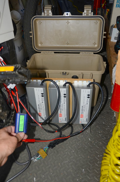
I obtained mine at $113 here:

http://www.powergatellc.com/mean-well-hlg-320h-24a-power-supply.html

$113 is quite expensive. Wouldn't something none branded that is 2-3 times cheaper worth it? http://www.aliexpress.com/product-fm/340130866-free-shipping-400W-48V-for-selected-M-W-brand-switch-power-supply-wholesalers.html
 
It all depends on what one wants. This thread is about a higher quality charging solution.

There are lots of threads on Meanwell clones, and they often work well.

Those supplies don't have built-in current limiting and are not out of the box suitable for battery charging. So you have to add hardware and hack the supply, spending time, money and increasing the risk of problems.

Those supplies have noisy fans and are not potted for protection against moisture and vibration.

They don't have 5 year warranty and support from a US distributor. Hacking the supply voids any warranty they might have had.

There are many choices.
 
Revised Plan

My first Gold Phoenix circuit boards have been shipped. These are for another project, not this one, but is the first time I've used DipTrace or Gold Phoenix so is an important test for this project as well, as I am using DipTrace for the new layout here, and would use Gold Phoenix for any moderate quantity run of boards.

I have made a little progress on the schematic and layout of the board for this project (in DipTrace). My current plan is to simplify the design for the first iteration and try to make something that works and is useful, but not try to accommodate the whole wish-list on the first cut. I'll probably use dorkbotpdx printed circuit board manufacturing for these (hopefully useful) prototypes and just get three boards.

To keep it simpler for better chance of success on this round, I'm considering a reduction in complexity for this go-round:

* use the Teensy board
* incude 5V voltage regulator
* include the 16x2 LCD
* include the Allegro current sensor
* have voltage sensors for supply and battery
* use a relay for power control, switch the high side
* include one pushbutton
* preserve the I/O plan for the full design so it can easily grow into that later
* put pads on unused I/O for expansion/experimenting

Below is a list of things NOT included in this revision, reserved for future upgrade.

Since we can change the board size easily we can make this board smaller, and make it larger later as needed later.

Time goal is to have first draft PC boards in process (being manufactured) before end of September.

So what can this simplified board do for us (depending on the software)
* check ambient temperature for a safe range (sensor internal to CPU)
* check power supply voltage for safe range before starting charge (low and high limits)
* check battery voltage for safe range before starting charge (low and high limits)
* control charge current on/off
* monitor charge current, check for max safe charge current and shutdown below a low threshold current
* keep track of charge time, monitor and shutdown on charging over time limit
* keep track of charge amp-hours, shutdown charging on excessive amp-hours
* battery voltage monitoring, shutdown charging on voltage out of safe range (max and min)

Display
* mode/state (RDY, CHG, FIN, ERR)
* status/errors (OK, HOT, COLD, PSUV, PSOV, AHOL, DONE, OC)
* power supply voltage (XX.XV) (shown when not charging)
* battery voltage (XX.XV)
* charge current (XX.X A) (shown when charging)
* integrated charge current (amp hours) (to XX.XAH)
* charge time (H:MM)

Things left to future revisions:
* battery pack temperature measurement (1 wire bus)
* individual cell voltage monitoring (up to 8 cells per controller)
* communications between multiple controllers (isolated serial)
* data logging
* more sophisticated user interface (knob, buttons, etc)
 
Alan B said:
It all depends on what one wants. This thread is about a higher quality charging solution.

There are lots of threads on Meanwell clones, and they often work well.

Those supplies don't have built-in current limiting and are not out of the box suitable for battery charging. So you have to add hardware and hack the supply, spending time, money and increasing the risk of problems.

Those supplies have noisy fans and are not potted for protection against moisture and vibration.

They don't have 5 year warranty and support from a US distributor. Hacking the supply voids any warranty they might have had.

There are many choices.

I didn't know current limiting was required for battery charging? I thought you need current limiting only if you charge your pack to the max voltage? For example, if I have a 20s pack and charge all cells up to 4V, so with a max voltage of 80V, I wouldn't need current limiting because I can charge my cell at max current until 80V.

Also for me, the 5 year warranty woudn't apply as I live in europe.
 
Cwah, the problem of current that he is referring to is on the meanwell end.

The supplies are designed to power systems that have brief bursts of higher current demands. So the charger can actually output more current than it can continually deliver. If you demand everything it puts out without regulating current (or modding it so it does so itself), it will overheat and die.
 
Right. Batteries demand continuous charge current which will overheat a supply that is not designed to safely limit current. This is an important and necessary feature for a battery charging supply. Fetchter's external circuit does this with a standard Meanwell. These LED supplies do it right out of the box with two adjustments - one for voltage and one for max current.

Purchasing these supplies from a local electronics distributor should provide the warranty feature. Of course what we really want are supplies that don't fail in the first place. Since we are using them well within their normal ratings, and these supplies have longer warranties than most others from the same manufacturer, it appears they expect these supplies are quite reliable, and I expect they will last. Time will tell.
 
Back
Top