Open Source DIY non-hub motors

You might enjoy this link to the aussie CSIRO motor also. https://endless-sphere.com/forums/viewtopic.php?f=28&t=13957&start=15


Sent from my iPhone using Tapatalk
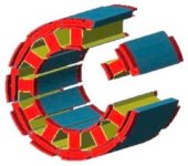
 
I will watch that, and search google + youtube once I know the proper search terms. I have been assured that when it comes to the drive sprockets with cylindrical bore, the 3/4-inch and one-inch ID are the most common (affordable, and available). I suspect 3/4-inch (19-ish mm) might allow one less tooth (whether pulley or sprocket) compared to one inch (25.4mm), but I'll do some looking to see.

I am certain cheap and available bearings of all types can be had in those sizes. Luke has been making a persuasive argument for lower voltages and higher amps, but I'm not sure what controllers would work for that.

An optical encoder (instead of halls) can be located on the outside of the motor case for easy access, plus they would be away from the heat. I suppose they could also be inside the case, but just behind an access plate?
 
FWIW, the Rotax Max engine sprockets that are made for #219 chain, have an ID of 19mm for the 12t and up, while the 11t has an ID of 17mm.
Generally, the available rear sprockets go from 60t to 99t.
A sprocket carrier is easily CNC'd from a plate of 1/4" alu, with splines to fit the freehub. (I should have taken a pic of the one I made...)
 
I don't have anything major to add to this thread, but, I was reading about the Evans axial flux pancake inrunner and the article
stated they use a copper rotor disc ? Would this be a solid disc or added on to a steel disc and how would this increase ability to make a more powerful motor ?

I believe they measure 10 and 5/8" OD overall ?
 
Luke/liveforphysics posted a video of an engineer from zero motorcycles discussing the motor design choices that they had made.

Biff and Luke both made a persuasive argument for using an inrunner with an "interior" magnet location, which simplifies assembly, but...the major benefit was that it allows the permanent magnets to run cooler, so the demagnetization temp of common magnets will not be a limiting factor concerning how hot the motor can be run. Temporary peaks being the driving factor, in relation to motor size and cost...the higher the temporary temperature peaks, the smaller the motor can be for a given peak power level, or...the more powerful a set size of motor can be.

https://endless-sphere.com/forums/viewtopic.php?f=2&t=48753&start=1500#p1227633
moter_f_img2.gif


Here is the IPM rotor from the common Cyclone 500W/650W/750W motor.

l30.jpg
 
I'm playing around with ideas here. The casing of the motor would have to be easily made from standard-sized materials.
Short of having a custom extrusion made, I looked at the available aluminum extrusions that could be suitable to make a casing of reasonable diameter, while also incorporating cooling fins.
Aluminum pipe seems very suitable for this, as the wall thickness is quite thick and can easily be machined to make the cooling fins.
In a diameter slightly larger than the BHT motor, the Schedule 40, 5" nominal size is interesting. Dimensions are shown Here

I have attached a drawing of what it could look like.
On the casing, there are 60 slots machined with a ball point end mill of 1/4", so it's pretty simple to fabricate. I kept it thin (0.050") to save weight.
Note that the casing doesn't have mounting feet like the BHT. It would be lighter to have the end covers serve as the mounting points. The end covers are bolted to the casing using 4, 5 or 6 long threaded rods of 6-32 size. There is no need to have threaded bosses on the casing for the screws, as they can lodge between fins to reach the side cover on the other side of the casing.
The inside of the casing is bored out to 5.060 to create a smooth surface for the stator to be lightly pressed-in, or alternatively being inserted in a hot (dilated) casing.
I wonder which would give the best heat transfer between stator & casing; A coating of white thermal compound on both surfaces before insertion, or Statorade smeared on both surfaces.

I think that for this project, taking a decision about the size and the fabrication of the casing is the first step to take, as the rotor dimensions then derive from this and the rest gets defined. Calculations can then be made to estimate the power available in this size.

A few things might be considered as "absolute must have" so the motor can have better efficiency and power than the Chinese ones, for the same size.
Thin laminations, 0.2mm or less.
Powerful magnets, SmCo maybe ?
Anything else ?
However, in the interest of simplicity, the motor should have a very low Kv, which is counter-productive to the goal of high power. But I believe that it is still very worthwile to have a motor of only 1500RPM @48V because then, a simple one-stage reduction to the rear wheel is sufficient. Also, the very low noise level generated by this simple drive is priceless when riding in the woods.

Re laminations, good stuff Here and Here
 
On shaft size, 3/4" is almost exactly 19mm, which is the standard ID of the Rotax sprockets for #219 chain. It's a case of one size fits all...

Regarding motor power, a minimum of 1250-1500W continuous would be a necessity, right?
 
3/4 inch is a good idea. I suspect its much stronger than necessary, but I believe that's a good thing. If the premise is that: "we may have a glitch in the supply of motors from China", then a size that is common in North American industrial supply houses is definitely the way to go. If the central mounting holes for the laminations are custom-cut, it can be anything, the shaft diameter is affected by sprocket ID sizes and bearing ID sizes.

#35 chain and sprockets are also a very common size for conveyor belts in industry and farm equipment. 3/4-inch bore is very common for that too. Regardless of the various benefits/drawbacks of #219 or #35, they are common in North America. Thanks!
 
For the windings, I really like the way GM uses flat "hairpins" that just press in.
If you handed me all the parts to their motor, I could just use my simple shop press and press in all the windings in one shot.. then just solder, weld, or wrap the points together on the otherside.

You get very good copper fill, with very little time spent. and time is money.
 
Yes, a ¾"/19mm shaft is stronger than necessary but as a weight saving measure, the center can be drilled to 1/2" without much loss of strength. However, I would not drill closer to 1-½" from the output bearing, where all the bending stress is concentrated.

A 19mm shaft will also allow the use of standard metric bearings which are cheaper that the american sizes, these days.

My interest in this project is driven more by the desire to have a better motor than the chinese offerings, rather than just as a preventive measure against a drying-up of the chinese supply. I'm convinced that we can design a better motor that will not cost a lot more to the end user. The part that is expensive will be winding because it is manual labor. But almost anybody who is talented for manual work can easily learn how to wind a stator, if provided with good instructions. So my thinking would be to have all the parts available to assemble a complete motor, with the customer doing its own winding work and assembly of the motor.

But before getting to that stage, we need the help of a good motor designer who can develop the electro-magnetic part, to fit our dimensional constraints.
 
How much will the laminations cost to procure and cut.
Then once the motor windings are done, heated and dipped.
Shipping costs for motors are very high, so being able to build one yourself would be very cool.

Its a fascinating concept to build your own motor.
 
I haven't checked the prices yet for the laser cutting, but it can't be very high. For a prototype motor at least. Then in production, you have to invest in a die to have the laminations cut.
Varnish impregnation and subsequent "cooking" isn't an absolute necessity. For example, the cheap chinese motors like the BHT, GNG and Big Block are not impregnated at all.
 
I'll do an in-depth write up soon, but I am impressed with the Porsche 918 hybrid motor. It couples a small V8 with a large outrunner, and the stator is segmented (easily done with DIY). The Koenigsegg also couples a large motor with a small V8.

https://www.youtube.com/watch?v=hLtxzPgDoSw

Rather than pick only one or the other, I now believe both the brushless radial outrunner with segmented coils...and also...the brushless Axial configuration (a la Lebowski/Mars) are both viable DIY formats. I will post screenshots of the vital points tonight.
 
Cool video. I like the idea of the separately wound segments. Interesting that the stator tooth tips are non-existent to allow this type of assembly. Perhaps the motor design experts can chime in on that... Looks like the coils are only retained at the end turns (but all that glue holds it together, i guess).
Too bad an inrunner would be impossible to assemble this way. Maybe for an inrunner, the coils could be pre-wound on stator segments that all get pieced together in the motor housing.
 
If you click on the video link I posted for the Porsche motor, one of the other video suggestions is the construction of the BMW i8 motor, which has a more conventional construction (BLDC inrunner, think GNG). The copper wire is wound around the stator-teeth by robots, and they can do things that are difficult to do with human fingers for any length of time, much less 24/7.

https://www.youtube.com/watch?v=oESBbRu32-E

This brings up the question, what about using segments for the stator of an inrunner, to make winding the coils easier? both are doable, so the difference is in making the rotor. Do as you wish, but...I would rather DIY an outrunner rotor compared to an inrunner rotor. For performance, and also for ease of construction...
 
PaulD said:
Cool video. I like the idea of the separately wound segments. Interesting that the stator tooth tips are non-existent to allow this type of assembly. Perhaps the motor design experts can chime in on that... Looks like the coils are only retained at the end turns (but all that glue holds it together, i guess).
Too bad an inrunner would be impossible to assemble this way. Maybe for an inrunner, the coils could be pre-wound on stator segments that all get pieced together in the motor housing.

The most significant drawback to what's usually refered to as an "open slot" design is the limiting of the ability to increase the flux density in the teeth to much beyond the level in the airgap. Some sort of cap, added after coil insertion, using laminated steel or SMC is conceivable.

The other drawbacks are the increase in detent torque and flux leakage into the slots.

I wouldn't say the technique has no merit in the case of inrunners. With a high slot count, you can still get a decent copper fill.

Separate stator segments require a sufficient amount of material in the yoke, to make the interconnection. So, they're not so practical for high pole counts.
 
Thanks Miles. When you say "sufficient material in the yoke to make interconnection", does that mean that a larger yoke cross sectional area is needed for a segmented stator than a one-piece stator?

Ron, too bad that i8 video doesn't show they get those wound coils into the slots. That seems like the tricky part.
 

Attachments

  • segmented_stator_1.jpg
    segmented_stator_1.jpg
    13.5 KB · Views: 5,568
  • segmented_stator_2.jpg
    segmented_stator_2.jpg
    13.7 KB · Views: 5,568
PaulD said:
Thanks Miles. When you say "sufficient material in the yoke to make interconnection", does that mean that a larger yoke cross sectional area is needed for a segmented stator than a one-piece stator?
It's more that it sets a lower limit. For mechanical purposes (some kind of joint for registration etc.) and for magnetic purposes (reluctance of the joints etc.).

The topic of segmented stators is covered quite well in Mechanical Design of Electric Motors - Wei Tong

https://books.google.co.uk/books?id=DizNBQAAQBAJ&pg=PA221&lpg=PA221&dq=segmented+stator+designs&source=bl&ots=tqaESPRV6S&sig=irKsCbY11UKDySIoV9StXGO9smY&hl=en&sa=X&ved=0ahUKEwjfytvA4KHRAhWlJMAKHS1ICJk4ChDoAQghMAI#v=onepage&q=segmented%20stator%20designs&f=false

I think it's fair to say that the big gain in copper fill with segmented stators is in comparison with machine wound one piece stators, not with hand wound ones. Machine wound one piece stators need to leave room in the slot for the needle to work in.
 
Some sort of cap, added after coil insertion, using laminated steel or SMC is conceivable.

Miles, if some sort of clever design could be arranged so that such a cap was attached after the coil slides on...is there any benefit to having the separate cap attach at the end towards the middle of the motor, so the center of the coils' core and the tooth-end that faces the outrunners rotor is the end that is one-piece?

I seem to remember you have some experience with FEMM, and you might know off-hand about any inherent drawbacks to having a two-piece coil core (regardless of where the break is located on the core)
 
Ron,

There are examples of that configuration in the link that I posted. If the teeth are separated, the body of the tooth acts as a lever in transfering the rotational force to the joint but you can take the advantage of using grain-oriented steel. If the tooth tips are connected together, you get flux leakage and can only use non grain-oriented steel.
 
Thanks Miles.
Apparently no particular idea is especially horrible or wonderful, but rather all variations have some minor benefit and drawback. So I guess we have to choose which compromise we hate the least?

Segments allow the optimum orientation of grain in the steel lamination (6% silicon). There have been many recent patents in motor design containing the least-horrible compromises which allow motors to be assembled by robots.

If using a T/I shape to a 2-piece stator-tooth segment, it is best practice to keep the section facing the rotor magnets as the "T" part. There are fewer eddy-currents where the magnetic-field shorting cap is placed against the bottom of the T-section, but stamping stresses at all the edges of the lamination sections raise hysteresis losses. (do laser-cut laminations have edge-stresses?).

I do notice E/I transformer (laminated) cores from microwave ovens DO work, albeit crudely so (to create a magnetic path in the "figure-8" shape).

ei-transformer-lamination-core-500x500.jpg


So, we can deduce that:

Drawbacks of additional segmenting outweigh benefits, and segment separations should be kept to a minimum

The tooth-end that faces the permanent magnets on the rotor is preferred for the T-section

Use of segments allows optimising local grain orientation, so why not? Starting on Pg 221

MotorDIY1.png

MotorDIY2.png

The pic below is from a 2006 patent, and...in a design that is not concerned with optimising grain structure of each tooth, laminations still have easy-assembly benefits if going to a 2-piece lamination. (side note, the drawing suggests that tooth-faces can be contiguous, instead of having a separation at their tip-edges.

View attachment 2

I count myself fortunate that the book Miles suggested doesn't just have several examples from which we can draw a theoretical conclusion, needing to be described only in words. Here below, we find an actual drawing of what I envision. An outrunner (due to the ease of constructing a DIY rotor, with no limits on RPMs), but the stator-teeth are discrete segments, to allow ease of DIY coil-winding on a jig. Its easier to discuss and critique when we all have a common drawing for reference.

View attachment 1

MotorDIY5.png
 
Back
Top