
marcos
1 kW
- Joined
- Nov 19, 2016
- Messages
- 348
So, heres another motor controller. I was a bit involved in Vedder's VESC design, big fan of Benjamin's work, and I've been pushing to get some funds to develop this inverter. I'm aiming at 400V and around 400A battery amps peak.
So, main design inputs:
* x12 650V TO247 IGBTs per phase, 36 for the complete inverter
* texas instruments ISO5852S reinforced isolation IGBT driver with extra current buffer
* laminated bus, made from milled copper sheets. transistors leads welded to these sheets
* optional, but desirable watercooling
* open source, made in kicad+freecad, available in github.
Here is a preview, its still a work in progress, far from being ready to prototype.
Schematic: (CLICK ON THE IMAGE for the latest commit)
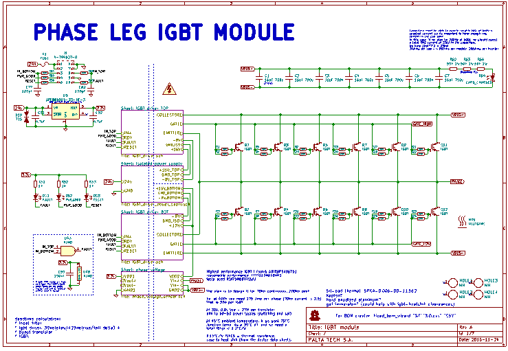
View attachment IGBT_board.pdf (probably old)


Here you can see the pcb layout better (click on the image)


Note the bus layers, from bottom->up they are VBUS-, VBUS+, PHASE, and pcb. The rationale behind this is that you get minimal inductance in vbus since both planes are very close, avoiding any current loop.
Film caps are placed in different directions:
(+ -)
(- +)
(+ -)
(- +)
So their internal current loops cancel each other. I got that from an app note http://www.mouser.com/pdfDocs/Cree-...or-Designing-with-Cree-SiC-Modules-part-2.pdf
When I say milled copper sheets, its because in the workshop we have a cnc and I think we can pull something like this

I never tried milling copper, I know its not that easy, but it shouldn't be impossible to cut a copper sheet. The cnc could also bend the copper 'leads', and even automate the spot welding process. Not that I'm keen to do that now.
Sheets can be separated with kapton or FR4. I kind of prefer FR4 because I can drill it precisely and it would help with the alignment of caps and transistors for welding, its critical to get everything solidly aligned to avoid bangs.
TO247 support is an aluminum heat spreader, 20mm thick. I drafted a 3D model of a simple milled watercooler that would fit the same way and provide a more even heat exchange and actual heatsinking. Not sure about how to press the TO247 against this heatsink.
About the schematic, its mostly based on a TI 22 kw eval board, with some extra thingies I learnt by reading and listening to smarter and more experienced folks.
The board is a simple 2 layer PCB, but when you count in the 3 copper sheets below it you can get a nice electromagnetic-wise design.
The brain would be a VESC board, I have experience in STM32 MCUs, Vedder's board has a 168MHz monster with fpu and ADC phase current sensing synced to the transistors PWM, CAN, RTOS, etc, and very open source.
So... I wonder how does this look to the inverter gurus? Is it an interesting approach to you guys?
I'm open to criticism and keen to learn, I could get some equations or guestimates very wrong and I won't notice until I start testing the actual thing.
So, main design inputs:
* x12 650V TO247 IGBTs per phase, 36 for the complete inverter
* texas instruments ISO5852S reinforced isolation IGBT driver with extra current buffer
* laminated bus, made from milled copper sheets. transistors leads welded to these sheets
* optional, but desirable watercooling
* open source, made in kicad+freecad, available in github.
Here is a preview, its still a work in progress, far from being ready to prototype.
Schematic: (CLICK ON THE IMAGE for the latest commit)
View attachment IGBT_board.pdf (probably old)
Here you can see the pcb layout better (click on the image)
Note the bus layers, from bottom->up they are VBUS-, VBUS+, PHASE, and pcb. The rationale behind this is that you get minimal inductance in vbus since both planes are very close, avoiding any current loop.
Film caps are placed in different directions:
(+ -)
(- +)
(+ -)
(- +)
So their internal current loops cancel each other. I got that from an app note http://www.mouser.com/pdfDocs/Cree-...or-Designing-with-Cree-SiC-Modules-part-2.pdf
When I say milled copper sheets, its because in the workshop we have a cnc and I think we can pull something like this
I never tried milling copper, I know its not that easy, but it shouldn't be impossible to cut a copper sheet. The cnc could also bend the copper 'leads', and even automate the spot welding process. Not that I'm keen to do that now.
Sheets can be separated with kapton or FR4. I kind of prefer FR4 because I can drill it precisely and it would help with the alignment of caps and transistors for welding, its critical to get everything solidly aligned to avoid bangs.
TO247 support is an aluminum heat spreader, 20mm thick. I drafted a 3D model of a simple milled watercooler that would fit the same way and provide a more even heat exchange and actual heatsinking. Not sure about how to press the TO247 against this heatsink.
About the schematic, its mostly based on a TI 22 kw eval board, with some extra thingies I learnt by reading and listening to smarter and more experienced folks.
The board is a simple 2 layer PCB, but when you count in the 3 copper sheets below it you can get a nice electromagnetic-wise design.
The brain would be a VESC board, I have experience in STM32 MCUs, Vedder's board has a 168MHz monster with fpu and ADC phase current sensing synced to the transistors PWM, CAN, RTOS, etc, and very open source.
So... I wonder how does this look to the inverter gurus? Is it an interesting approach to you guys?
I'm open to criticism and keen to learn, I could get some equations or guestimates very wrong and I won't notice until I start testing the actual thing.


")