Ping V3 Reports

StevenR

100 W
Joined
Jul 27, 2008
Messages
175
Location
Milwaukee, Wisconsin
I bought a Ping v3. It rocks at 35A+ continuous with no trips and minimum voltage indicated on the CA is about 49 volts with maximum of 1825 watts indicated and a 43A maximum. I will solder my shunt to get to 60A continuous after I break it in a bit (20-30 cycles is a target but it may actually be more before I get around to it) although 35A+ on a 5303 with 48V35A controller is almost enough - 60A may be overkill, except on accelleration and 5 second bursts are hardly continuous. I have 6 cycles for 60aH with the maximum discharge less than 10aH. I had to use it before it fully charged for the first time and ran it up and down 4-5aH once or twice before I fully charged it and let it balance overnight. Now it is basically on charge/balancing or discharging 24/7 for the next several months (until the snow flies and perhaps even thereafter) and I will monitor the cell voltages compulsively.
Pingv3andv2.jpg
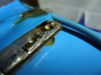
Better packaging. Shrink wrap even! The BMS is in a transparent shrink wrap tube with the charge FETS covered in blue. It came taped to the battery with clear packing tape and I haven't chaged that yet even though there are ugly little bits of styrofoam under it in places. The battery itself is shrink wrapped with plastic end covers under the wrap. Output wires are heavier than the v2 - 10 gauge versus 12 gauge, perhaps? I will post better pictures shortly.

New v2.5 BMS seems to balance effectively, if slowly. Most cells are at 3.79-3.80 volts on CV at 61.09V with a Ping 5A charger. One is at 3.74 and has come up from from 3.68 over the last few hours. I will watch it as I do laundry over the next couple hours to see if it comes up to match the others but 0.05V isn't much difference. Everything seems to be stabilizing nicely. The LED's are a nice touch and give a great sense of confidence that everything came up properly. It came with the charge leads seperate from the discharge leads (no common positive) with the charge plug attached. Charge FETs got quite hot at 3.5A. I will see how they do at 5A.

It was $798 with 5A charger plus $130 shipping. v2.5 is $598 with 2A charger plus $125 for shipping.

BTW: I have about 2300 miles and 300 charge cycles on a Ping v2. My Ping charger had too low a voltage (58.2V CV) so I set my Soniel the same. It never properly balanced. By the time I figured this out and reset it to 61 volts, it was sick and then one cell group went to 0.0 volts. Three or four others are at 3.3 volts. If I put a single cell charger on those cells they come up but then droop back to 3.3 over the course of several hours. I am replacing the one 0.0V bad group then will do a capacity test. I may do individual cell capacities first but I only have a 1A discharge Tenergy unit so each test will take a while. I have a total of three new cell groups and want to replace the worst existing ones. This will be my backup bike battery and will be split into two 24V 20aH packs for use in experiments like 90V screamers and great big parallel packs - Headways are on the way as soon as the boat docks.
 
20 cycles. 220 miles. All cells balance to 3.81-3.82 on the cheap VOM. Just did 65 miles on two cycles of 18.9 and 20.2aH back-to-back with an average for the whole trip of right about 25 MPH and have the pack on charge. These are the first two deep cycles - one out to rated capacity with no sag at the end and a minimum voltage of 47.8 vollts pulling 1750 watts. Maximum current of 42A on a 35A c'lyte controller.

300 miles and the pack is breaking in. Now it's about time to solder the controller shunt and see what I can break next. Hopefully, not my neck...
 
StevenR said:
...These are the first two deep cycles - one out to rated capacity with no sag at the end and a minimum voltage of 47.8 vollts pulling 1750 watts. Maximum current of 42A on a 35A c'lyte controller.


Wow that sounds like an excellent pack! I assume since the Version 3 batteries aren't on Ping's website that you had to make a special request; do you have any idea when he will make the V3 generally available?

-R
 
I've bought 7 of the 48V 15Ah V2.5 - 3 packs from Ping

Excellent communication, excellent service, very profeccional man!

I use them with the Clyte 35A 48V controller and the 9C 2907 motor on a 26".
and the 5A aluminum charger.

They all work fine!

Except one of the battery have the charging mosfet VERY HOT!! it melted and cooked the blue shrink! :shock: . but still working.. but not too safe..

I wrote to Ping and he will send me a new replacement BMS

I appreciate alot the 16 LED... they are very usefull... they act a bit lik ethe Tppacks BMS from GARY.

The charging time is about 3hours for an empty and balanced battery.

I personally tested every of them with a 2 ohms high load high power dummy load at 22A and all BMS have cut to between 15.2 and 15.7Ah ( avg 775Wh)

here is the overheated mosfet:
 

Attachments

  • P1070961.JPG
    P1070961.JPG
    56.4 KB · Views: 5,317
Just email him. He seems happy to sell them. Most motors don't need them but I buy into the "v2 isn't big enough for the 5303" school. I tore up my v2 pack but that may have been a balancing/ignorance issue. The v3 seems happy at 1750+ watts continuous. I am a bit concerned about the pounding it is taking though. I need to rethink my cushioning which is minimal. Some good closed cell foam...
 
What is the c rate supposed to be on a V3 pack? If 2c, then 40 amps would be ok, but I would hesitate to push it more.

Did the previous v2 pack run with the 5303? If so, and it wasn't balancing, that would end up like it did. But go ahead and solder the shunt if you have money. I'd be like, no way, and just run the 35 amp controller.
 
StevenR said:
I am a bit concerned about the pounding it is taking though. I need to rethink my cushioning which is minimal. Some good closed cell foam...

I found some nice foam at Big 5 Sports - it's used for gym floor matting. It claims to be "high impact" "anti-fatigue" closed cell foam. It was $24 for sixteen square feet. Could probably find it cheaper somewhere else though.

ebike.jpg
 
i always find foam in the dumpsters. the polyethylene dense closed cell foam stuff is great, and there is the stuff that they use for kneeling mats for gardeners.

but reuse discarded foam sheet to keep it outa the landfills because it is more than permanent.
 
Report this postReply with quoteRe: Ping V3 Reports
by dogman » Sun Sep 20, 2009 5:40 am

What is the c rate supposed to be on a V3 pack? If 2c, then 40 amps would be ok, but I would hesitate to push it more.

I believe it is 3C. The BMS is supposed to trip at 60A with peak current being 100A. I was tripping all the time right from the start on the v2 but I have not tripped at 35A continuous 45A peak. I don't think I can use 60A continuous on the 5303/26". I am getting about 40MPH on the flats - 45 or more on a little downhill. I want to solder the shunt to get 40-45A continuous although I might slip with the solder and see if I can trip it out. If I do, I will limit with the CA. I just want to get up to speed a little faster and with the front wheel motor even 1750 watts is about all that is safe - I was having fun keeping the front wheel under me on wet roads tonight. I have the rear/disk 5303 though. eBike v2 is in the offing. Rear wheel drive should take it - wheelies are the only issue, and I LIKE wheelies...

Except one of the battery have the charging mosfet VERY HOT!! it melted and cooked the blue shrink!

My charging MOSFETs get quite hot with the 5A charger. Do you think it would take a higher charging current if they were heatsinked and/or fan cooled? I have about 20 old CPU fans and I could easily mount one that would run when the charger ran. I understand the cells are supposed to take 1C charge but the BMS is only rated for 5A. From my posts, you probably know I consider ratings as suggestions - like stop signs...
 
i think you should be cautious when attempting high rate charging with the ping pack. i cannot recommend anything over 1/2C for the pouch type cells.

for the heatsink idea, i decided to add some 10AWG stranded to the end of my v2.5 signalab BMS to carry away heat and the current from the output. i made sure to encircle all the fets with the solid 14G first so the FETS would be held in place when the solder melted holding them onto the bus, and the wire around back allows current to flow through the through holes to the wire and it holds it off the surface just a bit, plus all the wire and solder is enuff mass to absorb the heat and then carry it into the 10AWG stranded.
 

Attachments

  • DSC00664.JPG
    145.7 KB · Views: 3,364
1/2C, 10A, charge is better than the 1/4C 5A charge and I think the charger I saw was 7.5A although I should be able to find a 10A somewhere. Will the charge MOSFETS handle 10A if they are cooled? I like the wire idea - heat pipe out the side of the bag although the bag is open now at 5A charge.

I melted the solder off a v2 BMS in about 15 minutes at 35A continuous output (that the wire idea would have cured it). The v3 is just warm at 35A continuous for 30 minutes...
 
if you now have the smaller charger, why not measure the temperature of the charging FET while it is charging? maybe try with the BMS sealed up and just the end of the thermometer resting on the top of the FET capsule sticking out side so you can read it.

then open i up and allow air to just go around it, then raise it off the surface a little and measure the temp when air circulates underneath the pcb too.

then test at 10A and see how hot it gets, then solder on the fat wire like i did to see if that carries the heat away, to see if it could still be more enclosed from the weather, but able to soak up the heat more with the cable. i shoulda done a before measurement myself, maybe yet.
 
I'll stick my little digital thermometer in my bag and try to get a measurement on the next charge - the bike got the night off tonight. I have foam packing in the top of the bag so I open it up when charging but I will try it both ways. I will try to remember to put a wrap of tape on it if I blindly stick it in the blue shrink wrap...
 
if you have glass type thermometer that would be best, but yes, make sure not to short anything down there. plastic straw around the metal ones. then watch the plastic melt, hehe.
 
I put on some heat shrink tubing. That will probably slow the heat transfer rate substantially but I will just stick it in and come back in an hour - everything should have equilibrated by then. I may just stick it in now and leave it. It shouldn't be in the way...
...I'm not sure where I can put it. I may need to cut the shrinkwrap to actually get it where it's hot. I will get it sort of in there but I will stop at the Walmart and get one of those wireless transmitter units if they are reasonable or even a wired indoor/outdoor thermometer. I keep opening the bag after a hard ride to see how hot it is. If I put a sensor on the hot spot, I can watch it instead of the road. Come to think of it, I have one of those that is sort of untasked right now. It has min/max functions too. Off to find it and putz...
 
heat shrink is alright, straw is cheaper, heh?

anyway, put it right on the charging FET over on the side above where the charging wire goes in. only that one FET on the end handles the charging current. so just put the tip of the thermometer right on that, and hold it with some tape so it stays in place.

this could be so useful to know. i don't know how many BMSs i have seen burned up and if we could figure the easiest way to keep them cool that would be like way rad.
 
Mega-putz! I took off the clear packing tape that was holding down the BMS and stuck it on with velcro. I replaced the little powerpoles with the big (50A?) ones then replaced the 50A fuse holder from Electricrider with some 80 amp units from Powerwerx to fuse both positive and negative. The 50 amp fuses will fit the new holder but I will keep an 80 in the negative leg. The old holder would tend to arc at the connections. I'll see if these work better. Sticking the BMS down with velcro will let me get at it from all directions. I am also thinking of taking off the blue shrink wrap and using some of the stretchy velcro wire wraps from ebike.ca. This is better than v2 but an even better enclosure would be nice. I would also like to fuse before the BMS in the negative and get the positive fuse terminal soldered right to the battery. I currently have a powerpole on the positive battery wire and another came on the fuse so that when you unplug the fuse holder there is a hot powerpole with nothing but wire between it and cell 16 positive. I also would like a bank of fuses for the balance leads.

How do you measure the cell voltages? I have been going at the exposed terminals on the back of the connector but I keep shorting things. Should I take the shrink wrap off or poke holes in it to get at the legs of the device (FET?) at the top of the chain of resistors? It looks like it should be at cell voltage if I am seeing the trace correctly - all the little resistors take the place of the big blue one on the old board.
 
yes, all the surface mount resistors take the place of the one leaded 22 ohm power resistor from before in the v1 signalab. but when the little led lights up there is also the avalanche current through the led which is bypassing the cell. so you have 5 surface mount resistors, marked 331 or 330 ohm. and the led has a resistor inline marked 102 so it is 1k ohm. if you have 5 330 ohm resistors in parallel, what is the equivalent resistance?

if the diode is in avalanche, what is the voltage drop across the diode?

assuming that the voltage across the shunt is 3.65V, what is the total shunt current through the 5 power surface mounts and the led together? this is your shunt current.

that will determine how fast the other cells charge. with the charging fet struggling to keep it within the range allowed. which i think is 3.9V for the signalab. so that would be max current at 3.9V.
 
Trouble.

I rewired with the big powerpoles and was putzing with the battery on the bench. Now I only get 46 volts at the output. I see the normal voltage across the balance leads - 58.8 volts or so. All the LED's light when the charger is on and I see charger voltage at the output. Is the BMS futzed? RATS! I need it for transportation. Time to bypass the BMS again. I didn't want to do it but I guess I need to have full override capability if I can't trust the hardware (OK, I may have screwed it up). I will contact Ping but I have to get to Pewaukee...
 
Yep, I screwed it up. Two balance leads are melted but still have cell voltage - they didn't burn or solidly short. I wrapped the bare wire and pluigged it back together. Still no output. I am about to cut the B- BMS input and install a pair of powerpoles so I can bypass. I won't go to high DOD and still have a 35A controller so I won't abuse too bad. Jeesh. I didn't think I would have to putz so much but I need to see the cell voltages and I must have shorted something while doing that. I need a save way to get probes on the cell outputs...
 
yes shorting the sense wires is very very bad. can you take a picture? if you put heatshrink over the section of sense wire that has melted, it should be ok.

the BMS is actually a big fuse itself and will shut off like a circuit breaker if your output shorts out and more than the 50A flows out. that is why that shunt is on there, and why you don't wanna bypass the BMS in discharge.

if you can repair the sense wires, you can measure sequentially off the plug and get the individual cell voltages there.

if you have low cells you will know right away. write them all down so you don't lose track and can compare them in the future. this is more important than people realize. having the history recorded exactly.
 
All the cell voltages look good. The sense wires are intact and taped up. I installed powerpoles right out of the battery, put the fuse right there on plus and minus and put the corresponding powerpole on the BMS. I ran the motor a little, bypassing the BMS (nothing connected - sense, input or output) and then hooked it back up. It charged normally but still no output. I am going to run 10aH out of it bypassed (I have to - this is not an intellectual experiment) then reconnect the BMS and charge while out to dinner. I will check the cell voltages again but everything is within 0.05V on charge and the low cells seem to bounce around - the same ones are not always low. Oh well, got to go...
 
i've seen sparks while measuring the cell voltages from the BMS. a probe sliped and shorted to balance wires for a split second. mine was ok. the ping BMS is quite resilient. try and fix it. it's probably a loose connection somewhere. trace the sense wires back to the cells if you need too.
 
The sense wires all seem good, measuring on the tabs at the plug. All cell voltages look good. The output just won't come on. I emailed Ping. Signing off...
 
monster is correct about a loose wire. if any one of the sense wires doesn't make good contact, then that cell will look like it has low voltage to the comparator and the comparator will shut down the opto line and that will cause the comparator to shut down the gate drive to the output FETs. you may have just burned one of the sense wires open.

check the voltage on the pcb by putting the probe on the shunts , and you can then measure each cell's voltage right on the BMS. that will be what the comparator sees, but shorting the sense wires between each other should not damage the BMS.
 
Back
Top