I just found this thread yesterday, and after some thought (and reading) decided it’s a viable idea if carefully implemented. First off some comments.
If you are using ‘start’ caps, you are looking for trouble (IMHO). They are NOT continuous rated. They are only connected during the motors startup in their intended application. You should be looking for ‘run’ caps, which are almost never over 100uF, and for a given capacity are physically 4 to 10 times larger than a ‘start’ cap. Don’t trust ebay sellers who often list start caps as run caps. Buy from knowledgeable sellers! These are large (50uF) run caps:
http://www.ebay.com/itm/260880062973
The hair dryer in a link in an earlier post doesn’t have a GFCI in it. It would HAVE to have a ground connection to be one. <edit> Alan B pointed out to me that the last statement is untrue.

GFCI can and do work with only 2 wires. <endedit> I would consider GFI to be essential for this circuit, so beware. They are commonly sold for heat tape (for water pipe), as here:
http://www.ebay.com/itm/320861725418
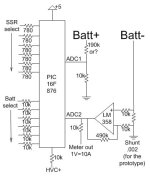
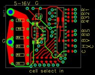
Here’s the circuit I’ve come up with to control one of these chargers. The LCD display interface isn’t included in the schematic and isn’t labeled on the board. RC4-7 are the data pins, and RB6&7 are the R/S and CS.


I’ve included a convenient test point to measure the current ‘C’ which will give 1V/10A. There’s also provision for HVC shutdown. BV connects to the Batt+, and R1-6 are outputs for multiple SSR.
For SSRs, I personally just use a triac with an optoisolator soldered to it (I’m cheap). Optoisolators with zero crossing detection don’t cost much more than without.
In an effort to make it ‘fool proof’ I intend to glue a pin header, hardwired for the digital representation of the number of cells, to the battery’s charge connector. If I eliminate a cell from a pack I would reprogram (rewire) the header (removing bad cells tend to cause packs to ‘change’ from time to time which could lead we fools to connect them at the wrong voltage). It would allow the processor to determine the charge voltage needed and could also function as the start charge signal. Obviously the charger’s battery connector would have to have a matching connector. I would connect switches to the 2 least significant bits so the human could communicate with the processor (with the battery disconnected).
To use programmable current I would probably add another couple pins to the header on the charge connector to program the current. 6 bits for 'S', and 2 bits for 'P'.
My choice of processor is based on the fact that I have some, and the software to program it. I have 18F parts that would give more usable pins, but my newer programming SW is corrupted and I don’t feel like fooling with it just now.

Also note that the PC board is designed to be hand built. If I had boards built I would redesign it (vias are really handy). I might even remember to include mounting holes. :wink: For the prototype I'll just etch it on an oversize board and drill holes wherever.

I’ll build the first prototype in the next few days and try to figure a way to test it (I haven't found suitable caps), so if you see an obvious error, please let me know. I just drew this this morning, so it’s POSSIBLE there’s a mistake.

Here’s a preliminary ‘outline’ of the program. How ‘steps’ are determined would depend on whether all the caps are the same, If you doubled the size of the cap for each SSR, it would be ‘digital’, With 10, 20, 40, and 80uF caps connected to 4 SSRs for example, you could control the current in 15 approximately equal steps:
Standby loop:
Display “ready”.
If either button held for > 1 sec, go to 'program setup'.
If battery connected, display cell count for n sec, then go to Main Loop, else go to 'Standby Loop'.
Main loop:
If cell count changes, shut down, display error message, and go to 'wait for disconnect'.
Energize least significant SSR. If current significantly less than setC (programmable), go up one step.
If controlled current goes above maxC (programmable), reduce 1 step.
If battery voltage > 4.25 (programmable) X cell count, reduce 1 step (and timeout next line so it runs).
Every n sec (programmable) shut down all SSR, and IF BattV > 4.2 (programmable) X cell count, display V, Wh, and/or Ah, and go to 'wait for disconnect'.
If HVC high, shutdown, display error message, go to 'wait for disconnect'.
Every n sec update display for BattV, time, current, and/or Wh (as programmed in setup).
Go to 'main loop'.
Wait for disconnect:
If display needs to change, call the display driver every n sec.
Loop (go to 'wait for disconnect') until cell select in = 0 (battery disconnected), then go to 'standby loop'.
I see I forgot to reconnect the processors Vpp the last redraw also. :lol: (fixed)(meant Vdd

)
Bob


