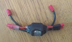
Pre-Charge Resistor

geeeyejo1

1 kW
Joined
Dec 1, 2012
Messages
375
Location
New Jersey, USA
Been reading posts on a pre-charge resistor being a good idea. Would this one work for my 48v 1000w hub motor with a 48v 15ah battery. My understanding is to wire the resistor on a separate positive circuit from the battery to controller and connect it first, then connect main positive connection to controller after system has powered up. Then pre-charge resistor circuit would be disconnected prior to riding?
http://www.ebay.com/itm/Pre-charge-Resistor-470-Ohm-5-16-Ring-Terminals-/390500021462?pt=LH_DefaultDomain_0&hash=item5aeb9d74d6
 
you can use a switch to turn off the circuit current in the BMS. when the battery is turned off, there is no spark. after you connect it to the controller, you can turn the battery back on. if it is a ping pack you can install the switch in the circuit that delivers the current that runs the mosfets so they are turned off when you open the switch.

you can do the same with the other BMSs that use the full pack voltage to drive the output mosfets.
 
Are you sure you need it for 48 volts? From what I have read here, they are mainly used for higher voltages 72 volts+.
 
dnmun said:
you can use a switch to turn off the circuit current in the BMS. when the battery is turned off, there is no spark. after you connect it to the controller, you can turn the battery back on. if it is a ping pack you can install the switch in the circuit that delivers the current that runs the mosfets so they are turned off when you open the switch.

you can do the same with the other BMSs that use the full pack voltage to drive the output mosfets.
What type of switch? I have seen the real heavy duty battery cut off switches - one of those?
 
dnmun said:
nope, a dip switch is big enuff. the BMS circuit current is only a few mA.
Ok, have not received my pack yet but it is a Ping type from Sunthing - looks like there are two wires that protrude from one end of the pack then all the wires on the other end that go to the individual cells to balance them. See attached link - which wire would get the switch?
http://www.ebay.com/itm/130656251541?ssPageName=STRK:MEWNX:IT&_trksid=p3984.m1439.l2648
 
Kent said:
Are you sure you need it for 48 volts? From what I have read here, they are mainly used for higher voltages 72 volts+.

I have a 48 volt lipo setup and it still gave enough of a spark that it was removing metal from the connectors.
The first time I plugged in my system it made me jump, I couldn't imagine what a 100+ volt system would do without a pre-charge. One use connector :D
 
dnmun said:
geeeyejo1 said:
dnmun said:
....ok then where would the switch go?

you install the switch in the circuit that supplies the current to the comparator that controls the output mosfets. when you turn off the circuit current, then the mosfets are turned off so the battery is turned off.
Ok - a bit of a electronics noob here - are you saying this is in the controller then? Is this simply installing a switch inline on a wire or does the board of the controller need soldering/etc? Not too comfortable with that...
 
I got these and they work great from 36-100V and higher. You don't want more than 150 ohm or you will still get a noticeable spark in most cases.
http://www.ebay.com/itm/10-PCS-10W-150-Ohm-5-Tolerance-Wire-Wound-Resistors-Power-Resistors-/160932756211
 
You don't need a stinking switch. Just wire it like this.precharge.JPG
 
wesnewell said:
You don't need a stinking switch. Just wire it like this.
Ok think i got it - Two connectors on right disconnect the battery for removal/charging, third connector appears to be wired on positive cable going to connector with resistor on both sides - If assume third connector is connected last, allowing resistor to initially handle current load, then when third connector is connected it carries the current from the battery - so no need to disconnect the resistor...
 
wesnewell said:
I got these and they work great from 36-100V and higher. You don't want more than 150 ohm or you will still get a noticeable spark in most cases.
http://www.ebay.com/itm/10-PCS-10W-150-Ohm-5-Tolerance-Wire-Wound-Resistors-Power-Resistors-/160932756211
Thanks for the suggestion - just ordered these and will follow your wiring diagram. If battery left disconnected then should be no issue with current draw from the resistor to the controller so will forgo the switch altogether...
 
geeeyejo1 said:
Ok think i got it - Two connectors on right disconnect the battery for removal/charging, third connector appears to be wired on positive cable going to connector with resistor on both sides - If assume third connector is connected last, allowing resistor to initially handle current load, then when third connector is connected it carries the current from the battery - so no need to disconnect the resistor...
That's it. Simple unplug both red wire connectors when not riding and leave the black negative connected all the time except to remove battery. To start riding, plug in the battery connection first, then the resistor bypass connector. If the resistor bypass connector comes loose while riding (has never happened to me) the voltage will drop to a point that will cause LVC to stop the motor, so you won't blow the resistor. Follow this sequence and you'll never have another noticeable spark. Just make sure you get in a habit of disconnecting both positive connectors when you get off the bike and that you connect the main positive first when hooking it back up.
 
Just thought I would post this up ( instead of using a switch ) It dont have to be 3 fuses (90A) or even a blade fuse, but this is the general idea.
fuseholder_antispark_.jpg
fuseholder_antispark2.jpg
 
Back
Top