Precharge for dummies

ryan

10 kW
Joined
Dec 3, 2009
Messages
638
Location
California Bay Area
Alright, please help me out here.

I have a switch and a resistor. Now what order do they connect?

The switch:
View attachment 1

The resistor:
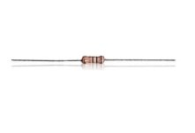
resistor.jpg

The switch has 3 poles: labelled [1],[2],[3].

I'm thinking:
pack --> [1]switch[3] --> resistor --> controller

Is this right?

What's the 3rd pole for on the switch? I tried the setup with aligator clip wires a 9v battery and a multimeter and can get the power to switch between 0v and 9v. But the LED never turned on. Is that because it needs 12v? If I use the second pole instead it only goes to 8v.

I'm going to be running this on an 18S setup with a paralleled 100v 100A circuit breaker between the pack and the controller.

I expect to push the switch on, wait 10 seconds, flip the circuit to on, push switch off.
 
Here's a drawing I made of what Jeremy Harris recommended to me:

F= fuse, R= resistor, the bottom switch is on/off, the top switch is a common button held in the off position by a spring. A fuse won't save the ESC (they blow too slow), but ya gotta put a fuse somewhere...

hold down button, wait a couple seconds, flip the ON switch, release button...

002.JPG
 
http://scriptasylum.com/rc_speed/nospark.html

Switches with 3 connections can be many types. The only way to tell what yours does is either to look up the specs for it or use an ohm meter to test it. My first *guess* would be it's a 2 position switch with one common. Each position connects the common to one of the other connections. I hope you aren't serious about that little resistor. Best bet would be a 150ohm 10 watt resistor. The one in you photo loks like a 1/8 or 1/4 watt.
 
hey, if you couldn't find the 150ohm 10 watt resistor, I wouldn't you be able to bundle those little suckers up in parallel to get the same ratings? :mrgreen:
 
The little resistor might very well be OK for this job. Remember you are not putting continuous dissipation into the resistor (it spends most of its working life short circuited by the main switch) just a pulse of energy while the caps are charged. This is 0.5 * C * V^2. So if you have 470uF and 72V that is a pulse of 2.4joules - not really enough to get a little resistor particularly hot. Note that the actual resistance has NO influence. So pick a resistance value that will give a current that the little switch can stand - if it's a 3A switch and 72V, a resistance of 24ohms would be appropriate (OK get a 27ohm - that's a standard value...).
Even repeated turn-ons are not a big deal because the main capacitors will not have discharged so far after a short off - time;- if the caps have gone down to 1/2 volts, the turn on energy pulse will be 1/4 as big....
 
sorry to but in here, but can someone please tell me what size resistor i should use for
an ezee 20A controller running at 59V fresh off the charger ? (48V ping V2.5)

i have been meaning to install a pre-charge circuit for some time.

Jason.
 
Theres a resistor value calculator in the link wesnewell provided above. I don't know all the places that would be good to get electronic components, but, I've had good luck at Digikey.com, the 50V capacitors I ordered were delivered in an envelope to my mailbox in 3 days.

Heres a group of threads on pre-charge resistors, info, plus also some part numbers so you can order right now if you are in a hurry.

http://endless-sphere.com/forums/viewtopic.php?f=2&t=23453&start=30#p342860
 
I'm basing 150 ohm on what I used, which is three 570 ohm 10 watt resistors in parallel for 170 ohm 30 watts. I still get a pretty good spark with only 2 in parallel, which is about 240 ohm. I've done 3 bikes from 12s to 24s lipo and controllers with 470-1000uf caps and it works good with all combinations. I used these parts because that's what I had. 100-150 ohm at 10 watts or higher should work well with most setups.
 
you could possibly use them for the lower current set-ups like mine. im not sure though.

i have a 20A controller limited to 15A for range and battery reasons.
i am running a 15Ah ping battery, and i like to keep the maximum current draw at 1C.

Jason.
 
Yes,I'm also onverting my ICE moto to electric, Diamondback,
with a 48v 20ah golden motor lifepo4 battery around 54v when charged and the normal draw is 40amp with a burst of 60amp.
So I'll try to add one 50amp thermistor or maybe 2x30amp in parallel to see how they work.
:idea: Maybe the voltage is not so important? and its all about getting one with the right resistance? and-or Amperage?

But its weird, there's no one in the forum that has tried Inrush Current Limiters, for the pre-charge circuit :?:
 
Mozart said:
But its weird, there's no one in the forum that has tried Inrush Current Limiters, for the pre-charge circuit :?:


i for one didn't know they even existed until i read about them in this thread.
maybe that's the main reason, they are not well known ?

Jason.
 
Diamondback said:
Mozart said:
But its weird, there's no one in the forum that has tried Inrush Current Limiters, for the pre-charge circuit :?:


i for one didn't know they even existed until i read about them in this thread.
maybe that's the main reason, they are not well known ?

Jason.


Well I'm not very proficient on electronics myself, I'm actually an electrician, but there are people here in the forum that are, and many more that have more than one EV.
Also these little things are used in the power supplies (chargers,computer power supplies etc.) for the same reason ,that is, to stop the arching when you plug-turn on the charger...
so what if it burns after some time, you'll spend less to change that, than the controller...

While searching for more information, I found this page: http://www.nerdkits.com/videos/motors_and_microcontrollers_101/
These guys use another kind of circuit to quench the spark by feeding it back to the motor through a diode. I'm going to mail them and try to see if I'll get more information on this.
 
Back
Top