2008 CRF250R - QS138v3 70H - ANT - Sanyo UR18650-RX 20s20p - Votol EM260

I actually did some of such poor-man's-scanner-aided-design for my EXC. I've posted about it on advrider, but for some reason my photos there seem to disappear :| and I recently had a NAS server failure that impacted a lot of my photos from 2024. Maybe they'll come back: 2021 KTM 500 EXC-F setup for dual sport

I try to copy all my data regularly (every week to month, depending on the data) to multiple offline harddisks, which alll then store in different rooms of the house. (back when I had multiple computers all working at the same time, I copied each one's data to all the others). Each backup doesn't overwrite the previous, but goes beside it, so a fail-during-write doesn't trash the backup and potentially lose all copies of something.

So far, except for one occasion a couple decades ago, that has prevented general data loss.

That time was an unusual moment, where I had to shuffle data among drives to make room, and they were all online at that moment, all writing data, and there was a grid failure that damaged the PSUs in several machines, and took the system down during write...I actually lost multiple harddisks, and had data corruption on virtually every other one. :( I still had enough redundancy in all the previous backups that I didn't lose very much data, but there was some.


But long story short, i used polycam to scan the plastic tail part, measured a known dimension to get the scale right, and then imported it as a reference mesh in CAD (I use Siemens SolidEdge because it's free and has no restrictive licensing like Fusion or OnShape).
Apparently even the free one is a "subscription". :( Subscription software is a total no-go, because it means my data is held hostage to their policies, as the software either has a time-out requiring updates to keep using it, or phones home to see if it's still ok to run. That means they can disable access to my data on purpose, accidentally, or simply by ceasing operations (or even by lack of internet access for whatever reason).

(there are a number of programs for various things that I'd love to buy (if I had the budget) but are subscription, so are unusable. Some companies have gone subscription and then gone back to "ownership" models because of customer loss, but very few do that. Most don't care what customers think and just shove their way (of whatever things) down the customers' throats).

I'm still using an ancient music-creation software, Cakewalk SONAR. I won't use their new stuff: the company went subscription, then went under, then were bought by another company who brought it back "for free" but with forced regular updates, logins to their internet site to even open the software on your own computer, and subscription...then they stopped updating the free one (but it still has all the forced updates, logins, etc so they can nuke it whenever they want, which has already happened multiple times because of various errors on their end), instead making a new paid-only subscription version that they also force-update. (if you don't update, it will just stop working as it can't login to their server and then you can't run the program or access your files). Users start threads about this issue all the time on their forums, and instead of the company replying or changing their methods to at least provide the *option* to purchase a perpetual license that doesn't have to ever go online/login/update/etc., they just lock all such threads, including any other kind of thread where someone mentions "subscription". Not very user-friendly company (but back when I got mine, they were the best at it).

Generally speaking, for parts that need a good interface with a mesh scan but otherwise are mostly for looks, I think Blender is a decent choice as well. Given proper scaling, you can create very complex, curved shapes very easily, much more easily than parametrically modelled surfaces. I know that stuff like BlueSurf and other advanced tools can help with that, but we're doing hobby 3d-printing not product design for millions for injection molding. I'll likely use Blender for CRF fairings if I ever get to that point (I'd like to cover the battery and cabling in additional layer of fiberglass on the outside).

I've been working slowly on learning Blender, but it's not an easy UI, it could be designed much better. (I haven't found any good UIs yet).


And finally, if you actually need a part to truly fit, not just conform to the shape roughly, the mesh is mostly used for clearance purposes, and in the cad you can create reference surfaces (planes for flats, cylinders for holes) to build the design off of parametrically.
For those kinds of things I can probably just do that to start with...the thing I "need" the scanning for is all the irregular surfaces and shapes that are virtually impossible for me to model even closely (much less accurately) without it. :)

But I haven't gotten to doing any of this stuff yet, so we'll see how it works out when I do--it might be easier to start with a scan either way.

One issue with scanners is that they require quite a powerful PC to work well. In my future workshop, I envision a connection to a server rack where the GPUs would sit, but right now dragging my PC to the garage is rather out of the question. A laptop would need to be quite beefy as well and they're prone to overheat -
I have some old rackmount HP servers that were originally used in sets to run 3D-rendering for animations, that I don't yet have setup for anything. They're not efficient, or quiet, but they do have more CPU and memory than my everday computer, and are running Windows10. I'd already intended one of them to be dedicated to 3D modelling / printing applications, and can easily dedicate more than one to that if it's necessary.

They don't have much in the way of GPU. I have an old "PNY NVIDIA GeForce GTX 560 1 GB Enthusaiast Edition" that can go in there, but might have to power it from a separate (external) PSU; it's probably better than any other GPU I have but that isn't saying much vs today's stuff :oops: It would probably be more useful (barely?) in the wolfy-bot project's server to help run whatever "AI" I find to do the behavioral controls. I figure it can't be very good since I see them on ebay in a quick search for $5 with free shipping. :lol:


so the photo-based scanning apps are actually really decent for the sweet price of 0 (well, Polycam itself has like a limit of scans or something, which i haven't hit yet - I'm also not sponsored by them or anything, I just found it to work reasonably well; I've used 123D in the past and it was markedly worse.)
How many scans? (you might have missed typing the number in?)
 
I haven't missed the number, I just forgot what it is. I dislike the fact that it's a subscription, but you get GPU processing of your input data for free, and then you can just download the model. Treat it as a service, not tool. That's why I use SolidEdge, that doesn't require any subscription. I think you need to type in some email but that's generally it, and you retain ownership of all your files.

As for reference surfaces, you might have not gotten that (or not) but the point is that CADs (and special scanner software, but I'm still thinking polycam or other photo apps here) have features for _extraction_ of those surfaces automatically. There's a vast difference in working between a mesh/point cloud and parametric shapes.

Won't comment on the NAS as that's already way off topic, let's just say I had backups on S3, just improperly (not exhaustively) configured. That's life vOv.

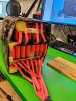
Back on topic, since the enclosure is on, I decided to do some prep on the battery to improve upon the third party situation. Hate to say I would have done a much better job if I did all of it myself...

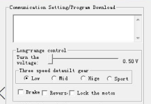
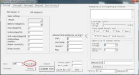
Feeling suitably inspired, I decided to see if I can get my controller up and running. It took maybe 5 minutes, and I got it connected to the software and programmed. I already know all the parameters by heart because I've read the manual so many times... Felt like I've done it before. I programmed a conservative 100A bus limit, the rest will have to be done with the motor connected.

IMG_20250130_233718.jpg
 
Last edited:
Åh, and one more thing. The Ant BMS app is really quite nice. Indeed no need for precharge resistors needed, it's easy to turn the battery off just from the app, in charge/discharge directions separately, and initiate the auto balance. I like it especially because that means I won't need any extra cables for a switch from the battery, I can turn it off remotely.
 
I haven't missed the number, I just forgot what it is. I dislike the fact that it's a subscription, but you get GPU processing of your input data for free, and then you can just download the model. Treat it as a service, not tool. That's why I use SolidEdge, that doesn't require any subscription. I think you need to type in some email but that's generally it, and you retain ownership of all your files.

As for reference surfaces, you might have not gotten that (or not) but the point is that CADs (and special scanner software, but I'm still thinking polycam or other photo apps here) have features for _extraction_ of those surfaces automatically. There's a vast difference in working between a mesh/point cloud and parametric shapes.
I appreciate the info...sorry for the OT. :oops:
 
No worries! We can always continue that in a proper forum section/thread and not spam this for other readers :)

I wanted to add a bit more about the controller setup. While it was easy, there were some quirks that might be useful for others to know.

Votol EM260S quirks

1) The controller has M6 mounting bolts, which are quite small for the currents they need to carry. Ideally the tabs would have M6 holes - I erroneously ordered my cables with M8, I'm pretty sure with enough tension that will be fine. As an alternative option, I was thinking about making adapter bolts with a cylindrical 8mm section and M6 thread, but I don't think it will be necessary.

2) The proper inputs to use seem to be the ones labeled B+ and B-. Because of the fuse, the B- terminal is unconnected to anything, and the unlabeled connectors is the actual B+ input to the controller - at least I hope that's the case!

3) To turn the controller on, you need an extra wire to connect the "on" signal on grey wire to the battery voltage (I also saw mentions of voltage higher than 35V). In the original loom, there's a purple E-brake cable that has a mating connector, looking like it could be possible to loop the two together, but they fit by accident - a separate cable is needed. I have to think about what I'll use to pull that signal out.

4) Just for laughs, I turned the BMS discharge off while the controller was on. It properly reported voltage gradually dropping (likely from input filtering caps) and kept working until 11.7V, which was the last reported value. I haven't tried it yet, but it looks like it could be possible to turn it on with much lower than nominal voltage for programming purposes. I know most people will likely do everything in situ, but it might be helpful to get the connection working near the computer desk like I did.

I won't be using a battery contactor or physical switch of any kind thanks to the BMS, so other than handling the "ON" cable, I have two current things to figure out.

Things to figure out:

1) BMS enable cable

there are two small black wires that come out of the BMS, and are used to turn it on if it (I believe) goes to sleep. I see two options here:

1A) keep them permanently connected and assume it won't drain the battery too quickly if it's not in sleep mode
1B) use some sort of a magnetic reed switch to energize it momentarily if the bike goes to sleep through the enclosure.

I don't want to add any more holes to the battery case than necessary, so using a magnet seems quite fun, also as a secondary theft prevention device.

2) Magnetic safety switch
speaking of magnets, that's the second one I'll have on me, on the handlebar. The obvious question here is what should it cut? I believe there are at least three options here:

2A) controller enable - that would result in a hard shutoff of the controller. Pro: should be quite reliable; Con: I'm afraid if it might hurt the controller if it happens with WOT, as it won't be able to ramp the current down gradually. I hope they have good flyback protection :S
2B) throttle in series - that's the "stupid, but works" way of doing it. Switch pops, throttle goes to 0, no input means wheel stops. Pro: should be also quite reliable unless the controller goes into some weird mode, the controller doesn't turn off; Con: perhaps a bit weirder wiring required.

Another thing to 2B is that I might want to experiment with a form of traction control in the future, and that would likely reside on the throttle line as well, so the cabling might not be that bad if properly planned.

2C) some aux controller input that makes the wheel stop - brake, sidestand, whatever... I have to trust the controller to "do the right thing" here, but it's trivial to wire up.

All of the wiring methods should fail into disable - e.g. if the switch fails, the cable is damaged or unplugged, it should behave as if the switch was tripped.

Eager to hear your thoughts on the above!
Don Cox has an interesting idea for the safety switch here. Seems like he suggests your 2C option. Good luck!
 
Last edited:
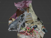
@amberwolf you might be interested in that one. Pardon the messy floor, thankfully that didn't pick up too much. I mostly wanted the area on top of the battery and i think that worked great. This took me about a minute to do.

Screenshot for peeps without 3D programs (you can open it in just about anything, though - just google "GLTF viewer")

1738428149654.png

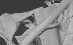
I mostly focused on one area so that one has more detail

1738428206737.png

Not enough to design off of, but to get a rough idea for panel sizing and cable routing? Sure.
 

Attachments

  • 2_1_2025.7z
    5.3 MB · Views: 0
And just to confirm, Votol boots with low voltage just fine, just reports it as 0.0 and immediate undervoltage fault (understandable). I'm not feeling great today, some cold or whatever, so instead of wrenching i might see if I can talk to it outside of the official app.
 
1738518231438.png

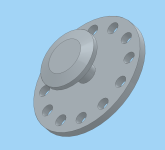
another 3D scan for another hiccup. Because of... reasons, I made the battery enclosure much thicker in the lowest "step" section than required. I was sure i checked it before that it won't interfere with the motor. I was sure the motor won't protrude past its mounting points and it will all have plenty of space.

Needless to say, I was wrong. I spent the entire afternoon mulling my options and I think that making another set of motor mounts to pull the motor further back is the most cost effective and simultaneously the best total outcome option. I need about 5mm of clearance, which I think I do have space for in the back. This time I'll likely 3D print a new set of mounts just to see how it lines up in practice. Thankfully with them being so cheap, it's really not much of a loss, plus I didn't spend any time actually fabricating them.

I added a new category to my build sheet: "wrong part ordered". I have no idea what I was thinking when I ordered the 50cm power cables. With the battery now in place, and the cables most likely exiting from the front, I added a whopping 30cm to them to make sure I can route them properly. Still keeping AWG1 (50mm2) though, despite the motor being just 20mm2 per phase. That was actually a more expensive mistake, but at least I get to keep the cables for some future use.

I've also finally ordered the intra-battery cables that will connect the BMS to the fuse and terminals, so once I make the cover, I should be able to fully assemble the battery. That's great because if in the meantime I can position the engine, I can immediately go to live controller testing - I don't need the final controller enclosure for that just yet, and it would be great to see a spinning sprocket.
 
I looked over the CAD files, tried everything with the swingarm on and decided I didn't make a mistake and I just don't have more clearance with the motor (i.e. I did a good job with that part). I decided to cut off the front engine mounts, which worked wonderfully. I left enough meat there for a new set of holes so I retain the possibility to mount the battery there, but now with everything in place I feel much better about the project moving forward.

I also did a test fit of the battery, and given the enclosure is bigger than needed, it was still a pleasant surprise that it... just fit:

1738527560028.png

Everything feels reasonably tight in there - no need to hammer it in, slides out easily, I might just add a bit of foam to cushion it inside. The whole thing with the enclosure weighed at 24kg.
 
Back
Top