Problem With Hall Sensors

Joined
Jun 8, 2011
Messages
127
Location
Tyngsboro, Massachusetts
Hi,

I have a 9c motor and recently the blue and yellow hall sensors started to only flip between about 4.5V and 5.5V. The green hall sensor works normally. I was surprised that two of them at the same time decided to misbehave so I decided to check for shorting between the wires. There is none, each wire is isolated, however I did notice that across the yellow and blue hall wires there is a resistance of 10K but this happens right at that small circuit board inside the motor. However, when I measured the green hall wire it was completely isolated from the yellow and blue. Is this normal? I tried replacing all of the hall sensors and yet the problem persists. Can anyone please help me?

Thank You
 
I found the little board toasts off a lot easier than the halls themselves. So the first roast and repair job on my 9 C motors is to rip out that board, letting the still OK halls continue to work.

Easy to toast that board, heat up the motor a bit more than usual, then stop and park. Then you get about 50F of additional heat spike when the wind on the motor stops. Just enough to roast that board.

Hard to believe you roasted the motor this week though. But it may still be a problem with a component on that board.
 
dnmun said:
something is wrong if you have 5.5V on the hall sensor. it should only be 5V on the red wire.

Thanks, I am reading 5.5V on the red wire. This may be because I took the readings when my battery is on the charger (60V) which is also the max voltage of my controller. I always thought it was normal that near max voltage the voltage to the halls starts to exceed 5V a little. The other weird thing I didn't mention is that the signal on the green wire was flipping between about 0.25V and 6.5V.


dogman said:
I found the little board toasts off a lot easier than the halls themselves. So the first roast and repair job on my 9 C motors is to rip out that board, letting the still OK halls continue to work.

Easy to toast that board, heat up the motor a bit more than usual, then stop and park. Then you get about 50F of additional heat spike when the wind on the motor stops. Just enough to roast that board.

Hard to believe you roasted the motor this week though. But it may still be a problem with a component on that board.

Thanks dogman, any idea of where I could buy a replacement board? Is there a circuit schematic some where of this thing to help with troubleshooting? Weird thing is my motor windings look like new and its been quite cold around here lately (single digits!) so I doubt it was the heat.
 
I don't know who routinely carries replacements for the boards. I just chuck em. You don't have to have it.
 
if you replaced the hall sensors already and you still have the same problem, why would you think the hall sensors were bad to begin with? did you damage them originally or just decide they were bad because you read something here that made you think they were bad?

i repeat, why is the 5V rail so high at 6.5V and do you know if your voltmeter is accurate? what is wrong with your controller if the 5V rail moves higher when you charge the battery?

how can you measure the resistance between two separate ICs on their sinking outputs? what is it you are measuring? they are only connected through the power and ground but there are a lot of transistors in between the outputs.
 
dnmun said:
if you replaced the hall sensors already and you still have the same problem, why would you think the hall sensors were bad to begin with? did you damage them originally or just decide they were bad because you read something here that made you think they were bad?

i repeat, why is the 5V rail so high at 6.5V and do you know if your voltmeter is accurate? what is wrong with your controller if the 5V rail moves higher when you charge the battery?

how can you measure the resistance between two separate ICs on their sinking outputs? what is it you are measuring? they are only connected through the power and ground but there are a lot of transistors in between the outputs.

I thought that it was normal for the 5V rail to move higher with a charged battery. I got this from talking to Justin about running a higher voltage battery where he said that if the supply to the hall sensors is above 5.5V when the pack is fully charged then a resistor mod is required on the linear regulator. This implies that a higher battery pack voltage can or will result in higher hall supply voltage. Is this incorrect? Obviously 6.5 is too high and this isn't due to my battery pack voltage because nothing has changed (ever) in that area. I don't know how the sensor can output 6.5V when the power connection is only a bit more then 5V. My experience previously was that the sensor outputs a little less than the power signal voltage when the sensor is on high.

I didn't know that it was the hall sensors but It was the only thing that I thought of that I could try (had sensors on hand). Switching out the controller for my backup didn't work and I don't have any extra small boards which go inside the motor (or another motor) so it was my only option to at least try something.

I did verify my readings with a second multimeter that I have and comparing the readings they are within each other by one or two hundredths of a volt.
I also switched out my controller for my backup and took some more readings today.


Here is a summary of the readings (wrt ground):

"->" means when rolling the wheel the voltage switches
If there isen't a "->" then it stays the same


@51.7V battery voltage


OLD CONTROLLER:
Red- 4.92 -> 5.74
Green- 0.27 -> 6.22
Blue- 4.51 -> 5.09
Yellow- 4.51 -> 5.09

BACKUP CONTROLLER:
Red-4.28
Green-0.23 -> 4.74
Blue- 4.00
Yellow- 4.00
 
if your 5V rail is pulled up to 6.5V then the 12V rail may actually be too high for the transistors that switch the mosfets then. the hall sensor ICs should withstand up to 20v so it should not damage them but it does look like only the green phase hall sensor is toggling.

can you post a picture of the two controllers so we know what you have and we can show you how to add another power input resistor to get the voltage input to the regulator down to reasonable levels. it should not be that high on a 16S lifepo4 pack. the 12V rail might go up to 15-17V but not so high that it pulls everything up on the 5V rail. you can measure it when you get the controller open. i doubt if that 6.2V would hurt the processor.

but you are not able to use either controller to make the motor run and the power lead, the red wire, is at a lower voltage than the green wire which should not happen. also the voltage on the red wire should not change when the hall sensor toggle. but it may be because there is some kinda short in the hall sensors that is also sinking power when the sensor toggles.

there seems to be nothing to do but get to the hall sensors again and then take a picture of them and post it up here. i wonder if the other hall sensors could have shorted to the power when you were soldering it together or maybe they are contacting somehow through the legs.
 
dnmun said:
if your 5V rail is pulled up to 6.5V then the 12V rail may actually be too high for the transistors that switch the mosfets then. the hall sensor ICs should withstand up to 20v so it should not damage them but it does look like only the green phase hall sensor is toggling.

can you post a picture of the two controllers so we know what you have and we can show you how to add another power input resistor to get the voltage input to the regulator down to reasonable levels. it should not be that high on a 16S lifepo4 pack. the 12V rail might go up to 15-17V but not so high that it pulls everything up on the 5V rail. you can measure it when you get the controller open. i doubt if that 6.2V would hurt the processor.

but you are not able to use either controller to make the motor run and the power lead, the red wire, is at a lower voltage than the green wire which should not happen. also the voltage on the red wire should not change when the hall sensor toggle. but it may be because there is some kinda short in the hall sensors that is also sinking power when the sensor toggles.

there seems to be nothing to do but get to the hall sensors again and then take a picture of them and post it up here. i wonder if the other hall sensors could have shorted to the power when you were soldering it together or maybe they are contacting somehow through the legs.

Both of the controllers are Infineon controllers from ebikes.ca and are 35A. I have taken a picture inside my older one.

Controller.jpg

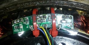
I opened up my motor again and took some pictures of the small board inside.
Board1.jpg
Board2.jpg

I had been running my motor with my lyen sensorless controller but for some reason after I took these pictures it stopped working. The motor just vibrates and I tried changing to other phase combinations even though the old one should have worked. The motor does the same thing on every single combination. Ugh, so many problems!
 
The supply to the halls is regulated. If you measure 5.5v between the red and black wires with your battery fully charged, it can't suddenly jump to 6.5v, unless it's open circuit voltage is 6.5v, and when you connect, something is drawing current enough to make it sag until the hall switches, which would imply that the hall is draining current while it's switched off, but not when on. I can't believe that.

The halls are more or less switches, so measuring resistance between the output wires is meaningless. If two are switched on, you'll get no resistance between them, and if the other is switched off, you'll get high resistance between it and each of the other two. Whether they're on or off changes with the wheel position.

Can you do the tests again at the same time. First, measure between red and black with the halls disconnected, then again after connecting. Then, measure between black and each colour while rotating the wheel.
 
d8veh said:
Can you do the tests again at the same time. First, measure between red and black with the halls disconnected, then again after connecting. Then, measure between black and each colour while rotating the wheel.

I have tested the hall voltages again and put the data below

@53.9V battery

"->" indicates change when moving the wheel

Older Ebikes.ca 35a:

Disconnected- 7.45
Connected- 6.11 -> 5.24

Yellow- 4.72 -> 5.34
Green- 0.28 -> 6.57
Blue- 4.72 -> 5.34

Backup 35A ebikes.ca controller:

Disconnected: 4.55
Connected: 4.28 -> 4.26

Yellow: 3.99 -> 4.00
Green: 4.73
Blue: 3.99 -> 4.00

Also I am now able to run my motor with my sensor less controller. I had broken a phase wire at the axle so it wasen't working before.
 
dnmun said:
so the broken phase wire was shorted to the hall sensors and destroyed them?

This is a possibility. I will be changing out the axle wires when I receive the wire and I wonder if it will be any different with a new set? At least it will eliminate any possibility of shorting in the axle or due to damage as the source of the problem.
 
dnmun said:
usually the hall wires get shorted to the phase wires inside the axle so you can check continuity between them. when there is no voltage present.

I did check the continuity between the halls and phases tonight, but there was no continuity between the phases and any of the hall wires.
 
so not now but there is the possibility that the phase wire that frayed open which is now wrapped with tape could have caused the hall sensor failure if one of the strands punched through the insualtion on the hall sensor. still trying to figure out why your hall sensors went bad since there was no evidence of overheating IIRC. one thing at a time tho.
 
So I replaced all my axle wires with Teflon wiring. My sensorless controller works. However the hall sensor problem diden't change. I am still getting the same readings as before for the hall voltages.
 
Hmm...well this silence is very reassuring. I decided to wire up the blue hall directly without that small circuit board and test it with a magnet when the stator is removed from the rotor.

Blue Hall off.jpg
Blue Hall on.jpg

Well what do ya know? It seems to work without that small board. So I wired up all of the hall sensors directly and tested them all using my controller.

New Halls.jpg

They all seem to switch just fine. The surprising thing is that the controller that was putting out >6V is now putting out 4.44V on the red wire with the halls connected. Both of my sensor controllers work now but I still have a question. Is there any disadvantage to removing that board? If it isn't necessary then why are the motors made with the board?


Also, In order to get the controllers (sensor or sensorless) to work after I redid my axle wires I had to change the phase wire combination. I checked the colors again and I am positive I matched up the colors correctly with the colors used on the stator when I redid my phase wires. In order to make my sensorless controller work I have to switch the blue and green wires from where they were before. In order to make the sensor controllers work I have to switch the yellow and green wires from where they were before. Is it possible I made some other mistake besides color mismatching to cause a phase color change? I'm not sure how it could be a color mismatch since I checked continuity between the connector with the phase wire in question and the correct winding inside the motor.
 
You're better off without the PCB IMO. The higher supply voltages? Who knows, maybe bad ground or bad connection allowed the +5V to drift up?

Here's a very useful thread about phase/hall combinations - http://endless-sphere.com/forums/viewtopic.php?f=2&t=48311&hilit=+Sensor

Scroll down a few posts, locate that excellent color chart and save it to your photos/documents folder. You might be able to find a hall combo that'll work with the sensorless phase color combo?

Nice feeling repairing these DD hub motors....
 
I havent' tried to use the pics to trace the PCB circuits, but I suspect they intended it to be a protection board for the halls in case of a short circuit--either to a phase wire or something else, and use resistors in series with the signal lines, and/or the VCC and/or ground to the halls.

There's a similar board in the Fusin geared motors I've opened up, and one of the "dead" ones that Dogman passed on to me after it had been overheated turned out to have various unknown SMT parts that had desoldered themselves from it during the overheating. I forget what I did to fix the issue, but removing the board (or bypassing the parts if they'd failed) would fix it, if they are indeed resistors in series with the VCC or ground or signals on the halls.


EDIT: While waiting for someone to call me back, i went back and looked at the board in your pics above, and traced out the paths:

Starting from the left side of the Board2.jpg pic: R2 is a pull-up resistor (5.1Kohm?) from VCC to signal. R1 is a series resistor (100ohm? for current-limiting? short protection?) between the signal output of the first hall (H1) and the output of the board to the hall wires themselves (blue, "A").

Same thing for the other two halls, and R3, 4, 5, 6. Then there's a capacitor (value unknown, C1), between VCC and Ground, very near to the input of those to the PCB from the hall wires (5V, -, Red/Black).

If it's like the Fusin motor hall board, there's nothing on the other side except for traces to go around things that are on this side.


I'm not sure what would cause the PCB to cause the failure you saw with it in circuit (that went away when it was bypassed/removed), other than perhaps a bad ground connection to the halls to the left of the capacitor. (the ground trace would be on the reverse side of the PCB, not in the posted pics, so i don't know what that looks like or where it's routed, other than on this side where you can see it go from "-" up to the thru-hole to the left of the bottom end of capacitor C1, and from there on this side to that end of C1).


EDIT2: In regards to the phase combo changing: When I fixed a wire problem with a 9C on DayGlo Avenger some time ago, I didn't have sufficinet lighting and somehow mixed up the blue and green wires inside the motor, and practically beat my head against a wall trying to figure out what had happened and why it didn't work anymore when I "knew" I had done it the same as it was before.... :oops: Dunno if it's possible that you did that, too, but thought I'd mention it.
 
"So what is that board meant to be doing?"

the little pcb is there to hold the hall sensors before they install them in the motor, preassembled, and it has the small capacitor to absorb noise on the power line. it holds the hall sensor legs out of the way and keeps them from shaking and flexing.
 
Back
Top