johnamon
10 W
Hi all,
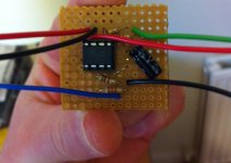
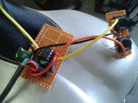
I have been working on a push button throttle. The protoboard soldering is all done and I plan to do the bike wiring this evening - so we'll soon find out it it works...
The throttle was created because I didn't find levers or twist throttles to be ideal, changing gear is a pain because I need to release the throttle temporarily which results in jerky power.
My new throttle is designed to increase the throttle output in 5% increments up to 100% and hold the power at the desired level (cruise control). The size of the increments may be increased or decreased, I just thought 5% sounded reasonable for my mid-power (<1kw) setup. The power may be regulated downwards by pressing the "down" button. The throttle increments are scaled from 1.3V (5%) to 3.5V(100%) with additional logic ensuring that 0% outputs 0v. The PWM throttle output from the ATtiny chip is smoothed to near true analogue via a low pass filter.
If the user hits the brakes - then the throttle cuts out completely (0v). An ATtiny45 microcontroller controls the throttle and responds to button presses & brake actuation. The current design requires a digital HIGH signal on the brake line, so around 3V or greater is required to be supplied to the microcontroller.
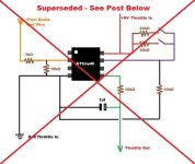
The circuit looks like this:


I am currently operating both "up" and "down" buttons off a single microcontroller input because I only have 2 spare wires available at the handlebars, this can be changed to individual button lines which would require 3 wires in total. With three signal wires - one could run a rotary encoder built into the bicycle bell - that'd be cool 8)
I'll hopefully get a video up this weekend of the throttle working
Thanks
John
I have been working on a push button throttle. The protoboard soldering is all done and I plan to do the bike wiring this evening - so we'll soon find out it it works...
The throttle was created because I didn't find levers or twist throttles to be ideal, changing gear is a pain because I need to release the throttle temporarily which results in jerky power.
My new throttle is designed to increase the throttle output in 5% increments up to 100% and hold the power at the desired level (cruise control). The size of the increments may be increased or decreased, I just thought 5% sounded reasonable for my mid-power (<1kw) setup. The power may be regulated downwards by pressing the "down" button. The throttle increments are scaled from 1.3V (5%) to 3.5V(100%) with additional logic ensuring that 0% outputs 0v. The PWM throttle output from the ATtiny chip is smoothed to near true analogue via a low pass filter.
If the user hits the brakes - then the throttle cuts out completely (0v). An ATtiny45 microcontroller controls the throttle and responds to button presses & brake actuation. The current design requires a digital HIGH signal on the brake line, so around 3V or greater is required to be supplied to the microcontroller.
The circuit looks like this:


I am currently operating both "up" and "down" buttons off a single microcontroller input because I only have 2 spare wires available at the handlebars, this can be changed to individual button lines which would require 3 wires in total. With three signal wires - one could run a rotary encoder built into the bicycle bell - that'd be cool 8)
I'll hopefully get a video up this weekend of the throttle working
Thanks
John


