• Hello ES! We could use some help to get us past the finish line on building the new knowledgebase for the forum.
    Can you donate? Please see our fundraising page. Thank you!

Rare Hall Sensor Error? *QS205 5kw + FarDriver 72680*

Noxen

New here
Joined
Jun 22, 2024
Messages
3
Location
Sweden
Hi.
Writing this thread is actually the only left thing for me to do. I've tried to solve this issue to my best without any luck.
Now I'm going to turn to you guys and really hope that you can help with a solution.
So, I run a FarDriver 72680 on my QS205 with a 72v battery but I just can't get rid of the Hall error message in the FarDriver app.
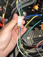
I know that the 205 has a spare hall but still I get the error code. Once I opened the hub to take a peek i couldnt notice any damage, all the hall wires seemed fine to me. However, the blue and yellow phase wires had a slight scratch which I had to cut away and solder.
The thing that I just cant figure out is that when I have the system powered on and tries to do this hall sensor test with my multimeter.
from my multimeter i put the negative on the black wire on hall sensor plug and then I go through the yellow, blue, green.
But every hall sensor is reading 9v, both the original and spare hall.
Why is that? I feel like I've been looked through the whole internet to find anything about this.
I would be thrilled if anyone can give me some tips or feedback. Just let me know if I should post any pictures.
Thank you in advance.
 
Hello,

can you please post the error and your hall sensors connections to the controller.

didi you try to move the stator and see the voltage change? voltage should not be the same and should change when you turn your stator.

this is for a scooter motor but is a good manual:

 
Last edited:
Thank you for taking your time to help!
Yes, I’ve tried turning the wheel while having black multimeter stick on black hall and red multimeter stick on every other cable on the hall plug, sadly without results. Both of the hall plugs keep sending 9v whether I turn the wheel or not.
I’ll throw in the pictures from the app and on the hall connector to controller.
 

Attachments

  • IMG_1238.jpeg
    IMG_1238.jpeg
    1.6 MB · Views: 22
  • IMG_1240.png
    IMG_1240.png
    924.6 KB · Views: 30
Well if the voltage is always the same in all the hall sensors and doesn't change when you rotate the stator you have bad sensors, in the other hand you say its a qs motor with 2 independent sets of hall sensors, I find it very odd that the motor come with 2 bad sets of hall sensors.

did you used this motor or controller before?
 
Yup, thats what I was afraid of. But I just thought it was strange that I'm reading 9v on the hall plug. I might be wrong but as far as I know they should only travel between 0 and 5v. I mean I havent seen anyone getting 9v in the hall, which got me kind of confused. Yeah no, the motor is old, the controller though I purchased recently. I've ordered bunch of hall sensors now so I'll be installing those when they arrives, probably worth changing the whole hall cable set too.
 
yes the halls should output from 0v to 5v.

Copy-of-psblog-16-2048x1152.png

The question is why you have 2 sets of bad hall sensors, yes you should check for some short between all this wires before soldering the new hall sensors of install a new cable set. Bad luck.
 
Может проблема в контроллере? У меня тоже qs 205, fardriver 72450, тоже перестали работать сначала один комплект холлов, потом второй.
 
Может проблема в контроллере? У меня тоже qs 205, fardriver 72450, тоже перестали работать сначала один комплект холлов, потом второй.

Translated to English is…

Maybe the problem in the controller? I also have qs 205, fardriver 72450, also stopped working first one set of heads, then the second.
 
I apologize for bringing up an old thread. I'm having pretty much the same problem. I have a QS273 with a ND72680. I hit a pothole, which bent the rim. Everything was still working fine with the bent rim. I installed the QS273 to a new rim. I didn't unplug the battery while re-spoking the new rim.(I should have)

I got everything assembled and when I turned the bike on, I get a single beep(hall sensor error) I bought a 9V brushless motor tester, the main hall sensor connector(this one was working before all this) turned out all 3 hall sensors were bad(Blue,Green,Yellow would not light up when turning the wheel). I tried the second set(reserve) hall sensors/connector. This one had a 1 bad hall sensor. The other 2 would light up.

I replaced all 6 with Honeywell SS41F. I checked before and after putting the motor back on the bike with the 9V brushless motor tester. Both main and secondary hall sensor were lighting up in sequence, which indicated a successful repair.

I turned on the bike still getting a hall sensor error. I log in on the FarDriver app shows hall sensor error, it will not Auto Learn(motor doesn't spin) throttle works and shows voltage.

I tested continuity from the FarDriver connector harness(controller side) all the way to the hall sensors everything checks out good. 9V tester confirms all the hall sensors are still working.

I grabbed a multi-meter and measured voltage from the Red Wire on the controller side hall connector and it is outputting 9.55V instead of 5V. Could the controller have gone bad? I just don't understand how all the all sensors went bad after just changing out a rim.

Could I be using the wrong hall sensors? My research shows the Honeywell SS41F should work with a QS273.

Any help would be much appreciated. I was hoping the OP would of said what the solution was.
 
Hall sensors won't just die without a cause. So something occured that damaged the halls, and has caused the controller to stop correctly reading them.

If the motor was left connected to the system, and the system was left powered on, during wheel manipulation where the cable gets moved around, then any internal cable defect or damage (which may not be visible externally) to insulation between hall signal (or power/ground) wires and phase wires can damage or destroy not just the hall sensors, but the controller's hall signal inputs. (if those are buffered then the buffers can be replaced, but if they are not, the MCU itself would be directly damaged).

A controller may also fail to read signals if the cable or connector is damaged, or not fully seated, etc.

Does your multimeter read the correct 5v from other places it should (throttle power, etc)?
If not, test it with a known-voltage source.
If it still reads high, the battery in the meter probably needs to be replaced.
If it reads correctly with the kvsource, but not on any controlelr 5v line, then the controller's 5v supply has been damaged.
If it reads correctly with the kvsource, and reads 5v on hte throttle/etc supply lines, but not on the hall supply, then you should first verify that your model controller actually sends 5v to the halls, and not some other voltage (12v is the next most common).

If the controller should be sending 5v but is not, the controller's supply is itnernally damaged and would need to be repaired.
If it should be sending 12v but is not, then again it needs to be fixed.
If it should be sending 9v, then it's working normally.

If you're testing the red wire and reading 9v with the *tester* (rather than the controller) connected to the halls, then that could be normal, as it's powered by a 9v battery.


(the hall sensors in most motors can usually take 20-30v on their supply pin depending on sensor version, and usually 30v on the signal pin's pullup source. These can be independent, so the sensor is powered with say, 5v, and has 12v on the signal line pulllup, or vice-versa, so it could be normal to read different voltages on these two. Depends on the controller design. )

As for which sensor to use, the most common is SS41 or SS411 types, but the specific type is dependent on what the controller expects for a signal, and how the magnets are laid out in the motor. It's simplest to just use the same model that was already installed in the motor. Most commonly hubmotors use open-collector bipolar latching types.

amberwolf, thank you for the reply.

What you have explained is starting to make sense as to what might have happened! Here is my theory.

The bike was working perfectly fine before I changed the rim and now I got a hall error. I should have disconnected the battery before doing the repair....because of that mistake, what we found-All 3 main hall sensors went completely bad, the 2nd set(reserve) had 1 hall sensor go bad.

When I opened the motor I inspected all the wires going into the axle and out the backside to the inside of the stator. Where the phase wires and hall sensor wires bend before the axle near the torque arm. I did notice the yellow, purple and red wires of the hall sensors had the insulation exposed(enough to see copper strands). This is what caused the main and 1 of the secondary hall sensors to go bad. Since I had the battery still hooked up I believe this might have damaged the controller as far as the hall sensor side of it.

I did electrical tape the red, yellow and purple wires independly where the exposed copper was showing before wrapping the motor cables. I didn't think much of it but now that I think about it more and what you explained, all the clues are pointing to the controller being damaged. Even after I repaired all 6 hall sensors and they appear to be working according to the 9V brushless motor tester, the damage has been done to the controller because I left the 72V battery connected. I'm going to test with a multimeter what you have pointed out but I belive it's going to be the controller.
 
Update

I grabbed my Multi-meter and I used the black wire from the FarDriver's main harness hall sensor connector for a ground. I then tested each of the signal wires from the Primary and Secondary hall sensors(going to the motor). The Yellow, Green and Blue are getting 2.3V and it drops to 2.18V when rotating the wheel, they never drop to 0V. One of them is reading like 1.8V and drops to 1.6V. It's the exact same reading on the reserve set of hall sensors(secondary set).

I then used the 9V brushless tester and I used the Black wire(ground) from the tester and I checked all 6 hall sensors. I'm getting 3.4V and they drop to 0V when rotating the wheel. This indicates the hall sensors are working perfectly fine using the 9V tester.

What does this conclude? I believe it's a controller problem. The 9V battery tester shows the ground wire is good from the Primary and Secondary reserve connectors. Basically the hall wires going from both sets is good according to the 9V tester. Did a continuity test from the controller harness to the it's hall sensor connector and everything is good.

Below is the 9V tester that I used. It's showing the hall sensors working fine.
 

Attachments

  • s-l1600.jpg
    s-l1600.jpg
    173.2 KB · Views: 0
What does this conclude?
If I understand your descriptions correctly, I’d say poor ground continuity from your controller pin used for the halls, internally to ground.
As there is more than one grounding pin available, I recommend disconnecting the battery. And checking resistance between battery negative connection on the controller, and all the grounding pins. To verity if it’s just the one pin, or if a good one is still usable.


Regards,
T.C.

Will do and report back. Thank you for the information. So just check all the grounds on the 30 pin connector.
 

Attachments

  • Screenshot 2025-10-14 at 18-03-28 Google Search.png
    Screenshot 2025-10-14 at 18-03-28 Google Search.png
    160.3 KB · Views: 15
If I understand your descriptions correctly, I’d say poor ground continuity from your controller pin used for the halls, internally to ground.
As there is more than one grounding pin available, I recommend disconnecting the battery. And checking resistance between battery negative connection on the controller, and all the grounding pins. To verity if it’s just the one pin, or if a good one is still usable.


Regards,
T.C.
Pin 16 which is the Black wire for the Hall sensor Ground is not getting continuity. I do get continuity from Pin 15 which is another ground wire that controls the Anti-Theft Power Supply.

All the grounds from the controller are posted below.
Pin 13 (Reverse) -No Reading
Pin 15 (Anti-Theft Power Supply ) *Beep* continuity good ground
Pin 16 (Hall Sensor Ground ) Nothing No Beep
Pin 18 ( High and Low level Speed) 4.16 on 20K omh scale
Pin 24 (Throttle Ground ) 2.5K on 20K omh scale

I believe the T4 1N4148W fast switching diodes around the 30 pin controller connector will fix the grounding issue. It would involve opening up the controller and removing all the silicone potting.

Should I just jump the ground from pin 15 and give it to pin 16? This should get the hall sensors back working again.
 
Should I just jump the ground from pin 15 and give it to pin 16? This should get the hall sensors back working again.

I’m concerned of the discrepancies between your pinout descriptions and the ones provided in the picture of wiring definition above…
If you could clarify the differences I’d feel more at ease with it.
But with this in mind, I recommend just taking connector wire 16 directly to battery negative and see if it works first.
I.E. Remove the wire from pin 16 and jump directly to battery negative, just in case pin 16 is shorted to something else Internally.

I would also encourage you to not use the “beeper” function and for all tests take actual resistance readings.

I believe the T4 1N4148W fast switching diodes around the 30 pin controller connector will fix the grounding issue. It would involve opening up the controller and removing all the silicone potting.
This is beyond the scope of my expertise, but an easy jump as mentioned above to start with, would seem reasonable.
 
I’m concerned of the discrepancies between your pinout descriptions and the ones provided in the picture of wiring definition above…
If you could clarify the differences I’d feel more at ease with it.
But with this in mind, I recommend just taking connector wire 16 directly to battery negative and see if it works first.
I.E. Remove the wire from pin 16 and jump directly to battery negative, just in case pin 16 is shorted to something else Internally.

I would also encourage you to not use the “beeper” function and for all tests take actual resistance readings.


This is beyond the scope of my expertise, but an easy jump as mentioned above to start with, would seem reasonable.
As for Pin 15 on the resistance reading it was 0.01 and would go to 0.00 ohms.

I like what you said I'll run the ground from the negative on the battery to Pin 16 for hall sensor ground wire. Thank you so much TommyCat you and amberwolf have helped me a lot!
 
The ground fix didn't work.

The black wire from the 30 Pin connector that goes to the main Hall sensor connector for the controller goes to Pin 26. I tested Pin 26 which is the ground for the hall sensors and get 0.00V @ 20K ohms and did a continuity test and get a solid beep. I guess the ground for the hall senor is working fine. I'm back to square one.

I now suspect the controller is bad.

I put a couple of pictures of the controller 30 pin connector and my FarDriver controller model number. Maybe they switched to a different pinout on the newer ND72680 controllers.

Pin 1 is orange(mine is Yellow/Green stripe) and Pin 2 should be Pink but mine is Blue. Also the hall sensor ground should be Black on Pin 16 but it's Yellow with a Red stripe.
 

Attachments

  • IMG_20251015_123434.jpg
    IMG_20251015_123434.jpg
    2.8 MB · Views: 11
  • IMG_20251015_125235.jpg
    IMG_20251015_125235.jpg
    1.6 MB · Views: 10
Last edited:
The wires seem to be in the correct locations, but with the pin numbering off between actual and diagram.

Stick with the wire colors for now to see if the outputs are correct…
I.E. Hall signals YELLOW, GREEN, and BLUE. With RED halls power +, and BLACK ground.
Test for correct outputs and power for the halls by back probing the connector when connected with power and key switch on.
Verify that they are going to the correct locations on the motor hall connector as needed to mate up with the internal motor hall sensors wiring.

This may help…
Testing BLDC motor's Phase Wiring - Hall Sensors and Wiring. - Electricbike.com Ebike Forum

I labeled all 6 hall wires and replaced them one by one so none of the colors got swapped around in the wrong order.

With the 9V tester. When I checked yellow, green and blue. They would go from 3.4V to 0V same with the Purple, Grey and White signal wires for the 2nd set of hall sensors.

When the controller is hooked up Yellow, Green and Blue go from 2.3V and drops to 2.18V. They never ground to 0V.

The controller is grounding the hall sensor pin at the controller Pin 26(black wire-hall sensor ground) that goes to the main hall connector.
 
The controller is grounding the hall sensor pin at the controller Pin 26(black wire-hall sensor ground)
Just curious, is this according to the white female plug, or the wiring definition screen shot?


Looks like 3 of the T4 diodes near the 30 pin connector are shorted.
Great call from earlier… keeping my fingers crossed.
 
Just curious, is this according to the white female plug, or the wiring definition screen shot?
I used the controller negative and tested Pin 26 on the controller, which is the black ground wire for the main controller hall sensor harness. Thanks to your suggestion on that part!

The wiring definition I got from the far-drive website but it could be a generic diagram to a different controller. Seems like my ND72680 is one of the older models, which could explain why none of the pinouts matched. Example, the website has Pin 16 for Hall sensor ground but mine is Pin 26.


Great call from earlier… keeping my fingers crossed.
Same here. I'm 99% sure this will solve the problem. This is a very rare example and I only seen 2 other people mention these T4 1N4148W SOD-123 diodes going bad will cause this same problem. The diodes are 75V 150mA so 1.5amps will destroy them.

Will update once the T4 diodes arrive in the mail. Thank you for the help again!
 
Update replaced 3 of the T4 diodes and can report no more hall sensor error. The controller is back working again.
I'm going to silicone the circuit board for vibration and waterproofing like the factory had it. I might not need to but it will help with the vibration. $1.50 in didoes saved a $300 controller.
I got to give credit to @zentechnician on YouTube, he is also a member here on the forums, he pointed out it's the T4 diodes, as he had the same problem with his controller.

I hope this helps others in the future!

Thank you Amberwolf and TommyCat/T.C. and zentechnician
 
Back
Top