Re-wind of a turnigy 80/100 (Now-tutorial w/Video)

I am encouraged you guys are being -pro active on the controller side....to be honest, I look at the data sheets of mosfet's & it may as well be in "chinglish", since 99% is uncomprehendable to me...I can ballance a crank shaft though...that has to account for something :p

Luke, I am seriously thinking of seperating a set of windings on one of my motors, for an attempt at running multiple controllers.

Ive seen axels home-made motors running that way...

I welcome anyones thoughts regarding the concept.
 
If you're going sensorless, I think having two sets of windings is definitely a huge advantage my friend. :) It would require buying 2 HV160's, but it should perhaps last, which is always cheaper in the long run than popping them like candy. But controller failures are the price you pay for super high performance BLDC motors, at this stage in the game, it's just something you gotta accept to play, I think KiM and yourself and most everybody doing RC builds understands that pretty well at this point. If I had a week off work or something, I would have a controller that you wouldn't blow finished. But I seldom seem to get more than an hour or two or freetime a day.... :(
 
liveforphysics said:
I think KiM and yourself and most everybody doing RC builds understands that pretty well at this point.

Everyone running higher powered rc setups do i know Definately do, if i wanted reliability i wouldn't be pushing the motor like have been, that said, i still haven't blown a rc esc through riding the bike Luke only by a making a stupid mistake when the motor was burnt out and powering the system up again and if you have seen any of my posted data logs Luke, it hasn't been by lack of trying LoL

KiM
 
As much as I fear blowing-up my RC controllers...They have been the highest performing set-ups thus far.
& suprisingly the most durable...I confess, I am a bit more carful when they are in the system.

I am still conviced that the torque potential of the outrunner topology is the correct path...we just need to weed out the bad configurations...until a superior controller becomes available.

I will wind bubba's 80/85 with the options to terminate in D/W & in "twin" controller mode.
See if we can't really flog the witch into submission.

& yes I accept that we are going to burn a few $'s looking for the edge. Thanks for the input.

etard (I have a pr inbound :wink:) Kim, I just call em 80's (I have another from bubba to experiment with & soon will have six to wind & adjust for my amusement)

kim said:
Reminds me Thud, mines not a 80-100 its an 80-130
I edited the OP to be all inclusive. (130/180) :mrgreen:
 
Nice Work Thud.

Regarding the terminology:
Concentrated windings are when a tooth is wrapped with a copper coil
Distributed windings is when a coil runs down one tooth (usually they call it a slot), then at the end, jumps over some number of slots and goes up that slot.

The motor you wound is obviously concentrated windings. The standard terminology for that is "turns per tooth". If you have different numbers of turns on different teeth, you would then specify the more complicated pattern, i.e 6-turns/7-turn tooth pair or something like that. The clearest way to describe the entire motor is to note the turns per phase.

Out of interest, for distributed windings, they usually specify conductors per slot, and then get more complicated if there are conductors for more than one phase in a slot.

So using that termenology, I don't understand how you got 6.5 turns per tooth, since in the picture it appears as though the start and end of each tooth's coil come out the same side of the stator. Do you have 6 turns on one tooth and 7 on the next with one wire and the other wire has 7 turns on the first tooth and 6 on the next?

Regarding separating the windings into 2 sets of 3-phase.
That would provide an advantage depending on how you set it up. To make it easier for the controller you would want to increase the resistance of the phase if you want to keep the same Kv. There are a few Kv's you could actually get from his motor. You have 2 pairs of teeth, per phase, and on each pair of teeth you have 2 seperate conductors, Which gives you 4 conductors per phase that you can connect in any series or parallel combination you want.

You could hook them up in 4 series which would give you the highest resistance and lowest Kv (and be required to use a single high voltage controller)

You could hook them up in 2 series 2 parallel with a single controller. This would give 1/4 the resistance and inductance per phase and 2x the Kv of the 4-series option. This allows you to run 2 controllers (one on each parallel group of phases) so each pase the controller saw would have 1/2 the resistance and inductance and 2x the Kv of the 4-series option.

You could hook them up in 4-parallel. This wold give you 1/16th the resistance and inductance and 4x the Kv of the 4-series option (if you ran with one controller).

However you could run with 2 controllers in parallel (each controller would have 2 parallel coils on it) each controller would then see 1/8 the resistance and inductance, and still 4x the Kv of the 4-series option.
You could also run 4 controllers in parallel, which would then give you 1/4 the resistance and inductance per phase and 4x the Kv of the 4-series option.

And for each of those phase configurations you have star and delta phase connection options, which would take a lot of time to describe.

You can figure out the Kv of a single coil, (using the spin-it with a drill and measure frequency / voltage) then put the values into a spreadsheet and figure out what option gives you the Kv / resistance / inductance you want.

-ryan
 
The dLRK winding uses two neighbour tooth to split the winding ( also called distributed )
the first tooth is wound clockwise, then the second ( right neighbour ) is wound counterclockwise.
In this case you have a winding being the last of tooth 1 and also the begin of tooth 2. That count as 1/2 wind, I guess?
-Olaf
 
Thud,

what are you going to use to lock the wires in place? CA, Epoxy, or some type of varnish?
 
Ryan,
Thanks for the input...
Thinking over you observation on the 6.5 windings...I am prolly just describing it wrong. There are 6 full wraps on each tooth but I only account for the the turns that fully circle the tooth. when we make the transition to the adjoing tooth there is a 1/2 length unaccounted for. I added this to the count...made sense at the time. But after thinking it thru, in reality its a 6-turn, :oops:

This motor for AJ, will most likely be terminated in delta & be called finished, & hope we havn't lowered the resistance too much to be controller friendly.

Here is a diagram for the seperated stator experimant showing terminations.
SPLITSTATOR.jpg


If I understand correctly, we are limited by the 14 magnet poles of the can. If we upped the magnet(pole) count to 16 we would have the option of ABC termination (& lose the LRK options)

:?: Is there enough info for you to simulate a few motor senario's (all of this will be directly applicable to the Colosus 7KW motors if my suspicions are correct)

If & when you get time, it would be cool to see some compairsons

The goal being: To tame these motors for the controllers & salvage as much of the power potential as possible.

Assuming Delta as the highest potential use, as a base line

Delta vs wye....straight up
Delta vs wye optimised. (less turns with more copper)
Delta vs wye optimised with 10 poles.(instead of the standard 14)

Thanks again. T
its my gut feeling the 3rd option will be the closest to the xring.

drewjet, I will use a little Vinyl-ester resin to lock the windings. (there are a few dabs of super glue as I was winding to keep things tight)
 
Sounds like you did indeed wind it 6.5t. The half turn that goes down to reach the neighboring slot does count, and to get back to the top you have to add in another half turn. From my understanding, we would call this a 13t motor since it is built like a dLRK.

Did you try to balance the half winds on each phase?
 
My understanding is that it doesn't matter if it crosses over the top or not. Every wire that goes down one side of the stator counts as a half wind.
 
John,
Yes I did, after re-reading Biffs post, I am convinced cottage industries (RC) take liberties with terminaology, Biff is describing what I refer to as LAP winding (as demonstraighted in the Astro's)
I will assume all the conection scenario's listed are for ABC-capable motors

This is wound DLRK for certain & I would call it 13T also from my park flyer experience. The 1/2 turn is either the last 1/2 of or 1st 1/2 turn of the tooth. Not a big deal. "tomayto/tomaahto".
 
Thud

The diagrams of the stator connections seem to be from a 16-pole 12-tooth stator, the 14/12 will be slightly different but the priciple is the same.

As for a simulation, I would need to know the magnet dimensions (height / width ) I think the advertised magnetic material is 45or 48MGOe so I would just use 45MGOe. I would also need the dimensions of the stator (tooth length, head size, outside diameter, inside diameter...all that. I could probaby do a pretty good estimate from the images in this thread, but it is faster and more accurate if I don't have to guess.

Do you have a good drawing of the stator / rotor with dimensions? I have some time this week to model it up and share the results with everyone on this foroum which I imagine a few people are interested in, and it will be interesting to see how accuratly the simulation predicts the output waveform / Kv.

Simulations for the different coil connection options will yield predictable results, since the power will remain the same (there is no magic happening by connecting things differetly which allows you to put more current through the copper in each slot). The input voltage and current that the controller sees will change with the different connection methods for a given RPM, but their product / sum will always be the same. The waveform will also stay the same. the unpredictible part is how the controllers will handle the different resistances/inductances of the different coil configurations.

I rethought about the number of turns, as someone else said, each time the wire travels the length of the tooth that is considered a 1/2 turn so to get a 6.5 turn motor the start and the end of the coil around a single tooth wold come out opposite ends of the stator, which now that I picture it, is probably what you have done. So you do have a 6.5 turn motor, I just wasn't thinking straight.

This helped me picture how the coils were wound to get the 6.5 turns
Tooth 1: down slot 1 , back slot 2, down, back, down , back, down, back, down, back, down, back, down slot 1
Tooth 2: back slot 2, down slot 3, back, down, back, down, back, down, back, down, back, down, back slot 2

In each slot you end up with 13 conductors, or 13 turns on a pair of teeth whith both ends of the conductors at the front after the pair of teeth is wound. So I would say you are right and it is a 6.5 turn per tooth arrangement.

As for the connection for AJ's motor, going with delta connection to start would give you the most power available at low voltage (high current) hopefully your FET's are fast enough and everything works. If you blow up a controller before even getting going you will need to rewind and connect in star, or add some inductors on the outside. I imagine it will be impossible to get all 6 conductors (both ends of each of the three phases) out of the motor casing since the wire is so thick, but if that were possible, that would probably be the best thing, since you could switch between wye and delta without any trouble at all. Having the 6.5 turn per tooth in WYE should give you about the same Kv as the original 8-turn in Delta.

-ryan
 
Biff,
Many thanks for this offer, I know time is valuble & I am not alone in apreciation.


the stator specs are:
OD: 65mm
tooth depth: 16mm
head width:12mm
Lamination thickness: .2mm
stator stack: 50mm

Magnet dimensions: 12mm wide x 50mm long x 3mm thick (n42 I assume)
14 poles in the can.
(I have a 10 pole option available)

An excellent source for this configuration of BLDC-PM motor is here:
http://www.gobrushless.com/kb/index.php?title=Brushless_101_-_Chapter_3

Ryan,
I am most interested in seeing the decomposing effect on RPM's if we leave the input parameters the same. I know the power potentials are always equal if we manipulate voltage & current.
experience shows that wye termination is the least demanding configuration for controllers. (especialy RC sensorless controllers) Just looking for the lesser of the compromises.
Thanks again, Todd.
 
Just a quick post to say thanks for publishing all the work you're doing on this motor, it will be invaluable when I come to wind one of the Colossus motors that's on its way.

Jeremy
 
I had a chance to run the simulations today

I attached the analysis in open-office format so that everyone could look and play around with it a bit.
It is a pretty basic spreadsheet, it takes the output from FEMM and does a little bit of math to figure out core loss, copper loss, input power and expected output power. There is also a second sheet in the workbook that shows the torque vs RMS phase current.

The quick analysis is that the Kv of Thuds re-wind should be about 140 in delta, and 80 in star (that is assuming 2 parallel conductors, 26 turns per phase)

The fill factor is around 44% (the slot area is 125mm^2 and the pair of #14 awg wires has a cross section area of 4.16mm^2, there are 13 pairs of #14 conductors in each slot)

The core loss at 8000-RPM shold be around 120Watts
The copper loss at 60A RMS should be around 140Watts (assuming the copper is 25 degrees C, so in reality it will be higher than that as temperature increases)

At 60A RMS, there should be about 8Nm of torque, so at 8000-RPM it should output 6700 Watts, which agrees with the input power (39V RMS * 60A RMS * 3phases - about 300Watts of loss)

The waveform looks pretty good, just a little bit sharper than sinusoid.

In the spreadsheet, the yellow boxes are the inputs, and things that can be played with. Some of them you don't want to mess with unless you really understand it. The ones that are most useful are the RPM and the Amps, and if you want, you can use the RMS amps per phase, and lookup on the torque sheet you can see how much torque the motor should produce at that current.

There are many things that are not accounted for in this spread sheet, but in my experience they are not that significant (such as skin effect as discussed in another thread). The biggest thing that is not in the spreadsheet is inductance. I haven't worked woth motors where the inductance is so low that it caused much of a problem so I haven't ever looked at inductance closely because it is very difficult to do accurately.

Enjoy .. I'll post the FEMM simulation and LUA scripts in a later post.

-ryan

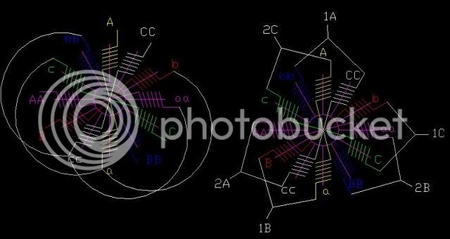
View attachment running_flux_0.jpg
 

Attachments

  • motor-analysis.ods
    89.7 KB · Views: 251
Here is the FEMM simulation, and the 3 different lua scripts I use to evaluate it, and the spreadsheet all in a .zip file.

new-flux.lua is used to determine the flux linkage at no-load, which is pasted into the spreadsheet to determine back emf.

Running-torque.lua is used to determint the torque of the machine while running at a given phase current (you have to edit the file to set the current). It also captures screenshots of the simulation, which is important because you want to see how the flux dencity changes during a cycle as the current is increased.

variable-torque.lua is used to figure out the approximate kt at various phase currents, to show when and how saturation affects the torque/amp ratio.

enjoy

-ryan
 

Attachments

  • For-Thud.zip
    96.4 KB · Views: 197
Ryan,
Thanks again for taking the time to do this.
Let me know if there is anything in my skill set I can do for you.
I will be a studying fool today at Lunch. :D

-T
 
Thud said:
I will wind bubba's 80/85 with the options to terminate in D/W & in "twin" controller mode.
See if we can't really flog the witch into submision.

Now I am going to have to find the thread that talks about twin controllers and figure out that there stuff. I don't know if my body is up to taking on that motor. Last time I fell off the bike I broke 7 ribs, punctuated a lung, and got a lot of road rash. That was with no electric motor. Your life expectancy is suppose to go up when you reach 40 because you are past the young and dumb thing that get you dead. Now I am well past 40, but still young and dumb.

Bubba
 
Well, time for an update:

I have the motor all assembled & running again.
1st thing I noticed is the cogging action is at least 200% over the stock winding. (this is what I would look for choosing stock motors back in the RC hand out days)

I imbedded hall sensors in the stator at 120 deg spacing & attempted to spin it up with el-cheapo Chinese controller I picked up on e-bay. As usual I have controller issues :cry: ...the cheapo controller spins up to 3/4 speed then screeches like its losing sync....to confirm that the issue was not the motor, I ran my other hall sensored motors with the same results.

Broke out a 6-FET with 4110's & it makes it spin to win (but got very warm quickly....6 FET's aint enough for this brute)
[youtube]xZHfWRpjf2k[/youtube]

I had high hopes for the 12-FET cheapo controller I fitted with 3006's...I have another older e-crazyman 12-FET I just picked up used on e-bay. I'll see if that works. AJ's prolly getting tired of waiting for this to come home.
 
Awesome Thud, What kind of amps is that 6 FET putting out? Did it get hot from just that video sequence?

Man, I can't wait to see you burnin ICE at the next bike race, you are gonna dominate!!
 
That's so cool! The sound on the video scared the beejebus out of the cat!

Just out of curiosity, did you ever try out the can with the N52's in it that I sent?

I figured it might make it a little bit less efficient overall but more torque at slower speeds, maybe better acceleration???

It will be neat to see it loaded up and running with an appropriate controller!
 
Shes alive!!!! Video of motor and pics of the 2 speed tranny all in one day Thudster!

I see what you mean by the blue anodizing turning greyish... no biggy mate, the
end of the motor wont be seen as much as the drive, if you can get
some darkish blue happening on the drive to show off through the grills
on the enclosure i plan to have it siting behind, it will break up all the black
ill have on the bike .... :D

As i said though mate in your own time no huge rush Thud whenever you can slip in some time to work on it :)

Shall post the video and pics of tranny n my build log to Thud :)

KiM

EDIT: Thud...i'll send you over my 12fet Infineon perhaps you can use it on another of your projects or scavenge it for parts? Its of zero use to me sitting here HECK it might even work for all i know haha Get it out next week to you anywayz.
 
Back
Top