Really strange KT controller issue, help please!

Daan

1 mW
Joined
Jun 11, 2023
Messages
17
Location
Utrecht
Hi!

I have the following issue:

Sometimes the motor assistance completely cuts-out and does only reingage when I stop pedalling for a second or two and/or release the throttle and then start again. The display stays on, it's only the motor that cuts out. It seems to can happen in any assist level, and only occurs within the 1-2 seconds after you start pedalling or engage the throttle. The strange thing is that it only does this like 1 out of 100 times. 99% of the time it works perfect, and then sometimes randomly it doesn't. When it happens and I just continue pedalling or use the throttle it won't ever work. You really have to stop pedalling to break the cycle or something. So it is also not the same a the brake cut-off for example.

My set-up:

Controller: KT48SVPRM-JBK001 22A (built-into Hailong battery deck)
Display: KT LCD3 V3.0 3CM
Motor: Bafang 500W geared hub motor

Display settings:

P1 100
P2 6
P3 1
P4 0
P5 15

C1 7
C2 0
C3 0
C4 0
C5 10
C6 5
C7 1
C8 0
C9 0
C10
C11 0
C12 2
C13 0
C14 3
C15 6

What I have tested:

- Changed the PAS sensor to one of KT (KT-V12L), did not make a difference, same issue.
- I had the feeling it might be a BMS cut-out, therefore I tested with a battery that doesn't have a BMS, although same issue, so also not BMS/battery related.

I am completely clueless, since it is so random. I have a lot of experience with KT controllers, but have never had these issue before.

These controllers and displays are ordered directly from the KT factory, I ordered 10 sets, all have these problem. I suspect some sort of weird firmware issue, someone has any thoughts?
 
Probably not every one...but ones in specific areas affecting specific things common to the problems, especially those as the groups that have the most symptoms in common.

Ok, update:

I measured the voltage on the throttle, while under load, and on standstill. Under load the voltage does not drop much, stays almost the same.

On bike A: around 4.4V
On bike B: around 4.2V

I therefore don't expect anything wrong with that, seems normal and within specification.

I do really have a suspicion that one type of FET is causing the problem.

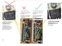
Each phase seems to have 2+1 FETs, so 3 per phase, 9 in total. 6 of the FETS of bike A and B are the same exact type, but 3 of them are different. See picture.

Question one, what is the logic behind 2+1 FET pee phase, 2+2 seems more logical right? Are the 2 for acceleration and 1 for re-gen?

I now have replaced the 3 MOSFETs that are different with some other brand mosfet (IRF8010PBF from Infineon) so far, so good. I haven't had issues yet, but I will do a long bike trip later today.

On the 2/10 broken controllers, 1 out of 3 MOSFETs were dead, which caused error code 6. It therefore seems most likely that all problems are related to that specific MOSFET.

Any thoughts?
 

Attachments

  • mmexport1687873995169.jpg
    mmexport1687873995169.jpg
    70.3 KB · Views: 5
Alright, another update:

I had swapped the 3 mosfets, the problematic controller had CRST041N08N 3QEB2799-4, I swapped those with IRF8010PBF INFINEON. Those seemed to have similar specifications.

I have written about 25 kilometer just now, and tried my best to get it to show the issue. I stopped and started with pedalling like 200+ times. It never showed any issues.

I will try to do at least 100 kilometers without issues, but looks promising so far.

So maybe the CRST041N08N 3QEB2799-4 are just bad? Causing cut-outs? Current spikes? And eventually failing? It is the part that ultimately failed on two of the controllers, nothing else failed.

So I am hopeful that this will be it. Will do some more testing and report back.

Let me know what you guys think! Thanks in advance!
 
Question one, what is the logic behind 2+1 FET pee phase, 2+2 seems more logical right? Are the 2 for acceleration and 1 for re-gen?
Somewhere around here are a few discussions on even numbered FET systems vs odd (6 vs 9, 12 vs 15, etc)


Why the FETs would cause the problem, I don't know. It could be that they require different gate drive than the ohters that work, and the gate drivers in the controller just can't do that job, and / or the firmware isn't using the right timing for those FETs to ensure correct turn-on/off. With that possibility, the system would also potentially allow shoot thru on the FETs, by turning on both top and bottom of a phase at the same time just for an instant, if the gates on the different FETs take longer to turn off, or turn on faster, etc, if the firmware's timing happens to be right at the edge anyway. .
 
Alright, another update:

I had swapped the 3 mosfets, the problematic controller had CRST041N08N 3QEB2799-4, I swapped those with IRF8010PBF INFINEON. Those seemed to have similar specifications.

I have written about 25 kilometer just now, and tried my best to get it to show the issue. I stopped and started with pedalling like 200+ times. It never showed any issues.

I will try to do at least 100 kilometers without issues, but looks promising so far.

So maybe the CRST041N08N 3QEB2799-4 are just bad? Causing cut-outs? Current spikes? And eventually failing? It is the part that ultimately failed on two of the controllers, nothing else failed.

So I am hopeful that this will be it. Will do some more testing and report back.

Let me know what you guys think! Thanks in advance!
Hi there, any update? I've got a 40a kt controller with less than 100 miles that started cutting out recently. I also eliminated the battery, inspected all connections. Only happens once it gets hot.
 
Somewhere around here are a few discussions on even numbered FET systems vs odd (6 vs 9, 12 vs 15, etc)


Why the FETs would cause the problem, I don't know. It could be that they require different gate drive than the ohters that work, and the gate drivers in the controller just can't do that job, and / or the firmware isn't using the right timing for those FETs to ensure correct turn-on/off. With that possibility, the system would also potentially allow shoot thru on the FETs, by turning on both top and bottom of a phase at the same time just for an instant, if the gates on the different FETs take longer to turn off, or turn on faster, etc, if the firmware's timing happens to be right at the edge anyway. .
fake fets would be my guess.
 
So I am hopeful that this will be it. Will do some more testing and report back.

Let me know what you guys think! Thanks in advance!

Thank God! I'm desperate! Bored of trying things, I'm already half crazy. I AM NOT ALONE!!

The same thing happens to me! And I've been looking and looking for the cause for 6 months and I can't find it.

The same thing happens to me, but not just a percentage of the time, it happens to me ALWAYS! Accelero starts the engine and after 4 seconds, it turns off. I have to stop accelerating and accelerate again for the wheel to turn again for another 4 seconds.

I put context:

I have a Magic Pie 3 motor, its controller burned and I put a new KT (KT48ZWSRKTB-SJT02LB) 22A controller in it. Everything was working perfectly. One day, I made a mistake and plugged an lcd4 into the bluetooth place. This controller died. I tried to repair it and couldn't.

This summer I bought a new controller, a KT48SVPRK-ff01L. This controller has 25A and in principle it was better than the previous one, it was sine wave.

I installed this new driver and nothing, from the beginning the wheel stopped at 4 seconds. It does not stop if the wheel turns very slowly at about 4km/h. Above this speed and without any resistance to the wheel, after 4 seconds it stops.

Now a month ago, I bought another controller from the same place and exactly the same. I rode it and it was doing the exact same thing too.

Now I bought a new lcd4, and it also does the same thing.

I'm desperate!
Now I understand that it is probably a thing of this particular controller model.

Do you know anything more about the subject?

Thanks
 
Last edited:
...

This summer I bought a new controller, a KT48SVPRK-ff01L. This controller has 25A and in principle it was better than the previous one, it was sine wave.

I installed this new driver and nothing, from the beginning the wheel stopped at 4 seconds. It does not stop if the wheel turns very slowly at about 4km/h. Above this speed and without any resistance to the wheel, after 4 seconds it stops.

...
tldr; looks the same on my controller, suspect fets or shielding issues.

long first post.

--

I bought one of those in December last year, it did this.

Since I'm rebuilding a existing sparta ion engine (the second model PMSM one with the funky magnet ring) I attributed it to offsets in the hall sensors, shrugged it off and went on with my work on it.

Put the OS firmware on it, worked like crap. Wrote a tool to figure out the hall angles, which worked ... for about a day, and when it worked with the corrected angles, it worked great. And after a day it stopped again. In the day I got it running I wrote a tool to figure out the hall angles (two are offset by about 10-15 degrees, enough to stall the engine) and the mechanical angle and it ran fine then. I'm working on making automatic angle finding an option for the open source controller software so stay tuned but I need a working controller again first to finetune it (timing was done on a pc over uart, which is a bit too inaccurate but good enoug to get the motor running, you can do 500k baud with the stm8).

The main problem is massive noise on the PWM-off signal, enough to effectively ground (< 0.6v) the hall's for about 400ns min to about 800 ns at worst which is more than enough to trigger errors on the GPIO inputs. I added some capacitors but this introduced new problems. The main issue is that the 10nF caps I added solved the V-drop-on-pwm-off issue but ripple currents got introduced somehow and caused it to fail again by the sinodal voltage pattern and it needs about a 1nF as well to dampen those as well.

I'll be getting new cables and pcb's for the motor to replace my ad-hoc version next week (the pcb will have 0603 cap spots on the hall sensor outputs). If it fixes it I'll let you know. Or if I find out what the problem is. I'm also going to some different sensors which are more sensitive (by about a factor of 4) just to be sure it's not a magnetic thing. I'm 99.999% sure it isn't but the new halls are less caring about input voltage as an added bonus.

--

When I put my scope on it, all hall sensors get drops in voltage exactly on the pwm-off signal to the FETs. Apperantly is a bit too much for some parts is my (un)educated guess. When it worked for about a day I'm not sure why. Maybe it's the cold, but I've been unable to verify that but it was about 10c colder that day in the room I'm testing in and the next morning it was as good as cow manure again.

The drop and ripple is present with and without the halls attached so adding caps will not "solve" the original problem. My main suspect is either shielding or bad parts. I haven't looked into the FETs really, they look genuine ST 110N7F6's (or very good clones) and CRST041N08N's which look more fake. I'll replace the CRST's if I can get my hands on some cheap IR ones but the local stores only sell 50A versions so I'll have to order abroad which will take a while.
 
When I put my scope on it, all hall sensors get drops in voltage exactly on the pwm-off signal to the FETs. Apperantly is a bit too much for some parts is my (un)educated guess.

Speculation, but maybe some things to check:

Best guess is there is a ground issue--the hall supply ground is lifted, so relative to that the voltage is less? Where is the ground when measuring the voltages?

If it's not the supply voltage you're referring to, remember that the halls are "on" when their outputs are at ground (not when at the pullup voltage).

In that event, the drops in voltage (if on the actual signal lines) would probably be from a drop in supply voltage from the 5v bus the pulllup resistors are fed by--sometimes that's the same as the hall supply bus, and sometimes there's a diode between teh 5v bus for the pullups, and the hall supply, that drops the hall supply by the amount of the diode drop. If that drop is enough, then depending on the specific hall sensor model used, it might be close to it's minimum supply voltage, and any brownouts of the main 5v bus from internal loads would be enough to cause undesirable operation.

If the 5v bus in the controller is all from a typical 78xx05 type, maybe the controller's hardware plus any external stuff (halls, pas, throttle, etc) is loading it beyond it's ability to supply current, so it's voltage drops... but since the 5v regulator is usually fed from a 12v or 15v regulator that itself supplies the gate drivers for the FETs, maybe the gate drive current change at those times you see the problem is loading the pre-regulator so much that it drops below what the 5v regulator requires to operate, browning out *both* busses.
 
Where is the ground when measuring the voltages?
I'll recheck specifically with the ground of the halls, but the scope's signal line Vdiff is on average about around the 5v mark if I remember correctly and referenced to the ground of the PSU.

and sometimes there's a diode
I'm pretty sure there is but I'm not sure it's on the hall signal side only and not the 5v bus of the entire region of the board. I'll have a look tonight. There are three 2.2k pullups connected to a 5v bus which also acts as collector/base/emitter (no clue what kind it is, has no markings) for a sot23 transistor. The part of the board is covered with wires, it's a bit hard to see what goes where.
The hall's I'm using now are ss411p's which have a 2.7v min. I'll check the 5v bus to see any drops there.
But ... they have internal pull ups which might not be the best solution thinking of it, but it was what I had laying around. The new ones arrived yesterday evening. It also would not explain the same issues other people would have.

browning out *both* busses.
Sounds very plausible.
I'll look into the power output of the regulators and check what is happening, maybe it's easy to spot a drop there.

The Vbat is regulated by a LM317T supplying 12-ish V, it can do 1.5A, if it is a genuine part I'm sure it can cope with the power requirements of the entire board and some.
The 5V rail is powered by a CJ78L05 as you mentioned. Should do about 250mA@12V maybe I can replace it if I have a better one laying around.
Some 100A+ FETs should arrive later this week, they are a bit less powerful than the ones installed but since I won't be running it at full load anyway it should be fine. The rest of the specs are either equivalent or better (especially the rise time). We'll see if it fixes anything.

I might also heatsink the LM317 to be sure since it generates a considerable amount of heat. Or move it altogether as the caps around it will like that even more.

Enough work to do tonight it seems. Thank you for the input!
 
Last edited:
I'll recheck specifically with the ground of the halls, but the scope's signal line Vdiff is on average about around the 5v mark if I remember correctly and referenced to the ground of the PSU.

Do you mean the ground of the PSU running the controller under test conditions, or do you mean the internal controller PSU (LVPS, low voltage power supply) that creates the 12/15/5v/etc out of the battery voltage?

(they should be the same, but depending on where on the ground plane the scope is connected vs how the ground plane reacts to current flow to/from the phase FETs, they might not be. )


I'm pretty sure there is but I'm not sure it's on the hall signal side only and not the 5v bus of the entire region of the board. I'll have a look tonight. There are three 2.2k pullups connected to a 5v bus which also acts as collector/base/emitter (no clue what kind it is, has no markings) for a sot23 transistor. The part of the board is covered with wires, it's a bit hard to see what goes where.

That sounds as if the controller might be designed to be able to turn the pullups off. Why, I can't imagine, for a KT. Some controllers able to run high-current low-inductance motors would make sense to do this, so they can turn on a 12v or even 15v pullup supply instead for a greater signal-to-noise ratio (but they would also have to have a buffer between that and the MCU that translates that down to the MCU I/O voltage range).

(most of these open-collector halls can take up to 30V on their outputs, regardless of the input supply voltage).


The hall's I'm using now are ss411p's which have a 2.7v min. I'll check the 5v bus to see any drops there.
But ... they have internal pull ups which might not be the best solution thinking of it, but it was what I had laying around. The new ones arrived yesterday evening. It also would not explain the same issues other people would have.
This one?

Since they have internal 10kohm pullups, you might want to disconnect the controller's pullups, otherwise the hall has to sink even more current to ground the pulled-up voltage, and so you get more potential for noise in that part of the signal.

FWIW, the reason they use OC output halls is probably to keep the phase noise off the 5v part of the signal to the MCU, and limit it to the ground part of the signal. I don't know for sure, but I expect that simplifies software design of denoising, etc.

If the hall could sink more current it could make a more stable ground, and do a better job of noise rejection. There's ways to do that by adding larger transistors to be driven by the output of the hall, but that's pretty complicated.

It's simpler to change the pulled-up voltage and buffer the results to the MCU, and probably give you better gains.

It's "better" to move the entire position sensing out of the motor so it isn't being crapped on by the phase currents and stator fields, and use some external optical or magnetic encoder. Not as cheap to build by the bucketload, which is why they do it the way they do.
 

Attachments

  • HWSC_S_A0012826569_1-3073204[1].pdf
    126.9 KB · Views: 0
they should be the same
They are, few mv oscillations but nothing of interest.

That sounds as if the controller might be designed to be able to turn the pullups off.
Looks like that was the intention but then was ignored along the way. The interesting part is the pullups are now connected straight to 5V, but the HE signal is at ~4.6v via a diode (which acts as the supply for the hall sensors) isn't.

Since they have internal 10kohm pullups, you might want to disconnect the controller's pullups,
Yes, those. I switched them out yesterday but forgot to press the post button on the message... They still show the voltage drop but it's now in the <100ns range and it's not enough to trigger the GPIO pins anymore for the looks of it.

I also found out one of the phase wires got damaged by me opening the motor a few times to check on the halls and touched the chassis. It got me walking in circles for a while until my continuity meter started making a 15.5khz signal... Which I guess introduced capacitive coupling (since the entire chassis was a phase wire now) making everything much-much worse and unusable but the orignal signal is still there after fixing it.

Since swapping the halls for non-pullup ones did the trick I'm going to leave it at that for now but I still find the voltage drop odd and if I get anomalous hall sensor readings again I'll continue looking into it.

Thank for all the suggestions! Hopefully someone can use it for future reference as well.

It's simpler to change the pulled-up voltage and buffer the results to the MCU, and probably give you better gains.

It's "better" to move the entire position sensing out of the motor so it isn't being crapped on by the phase currents and stator fields, and use some external optical or magnetic encoder. Not as cheap to build by the bucketload, which is why they do it the way they do.
They kind of did it with the motor I'm using: The hall sensor ring is on the inside but away from the coils near the center of the motor.

I measured the signal on the MCU side and the drop looks short enough now to not trigger the GPIO pins, or at least not within response time of the inputs and otherwise not enough for the software to care, and if it does i'll add a debouncing stage in the software if it's just one or two flips.
I don't think upping the voltage is a good idea since there are too many components attached to the 5V it's on and I don't want to risk butning out components without markings on them.

My main goal now is waiting for the PCB's so I can permantly attach the hall sensors in the correct position (it's now electrical tape and hope holding it together for testing) and that should do the trick for me not opening the motor again. And then adding a learning feature to the open source software since I'm 100% sure the default will not work. Shouldn't be too hard, I just have to find a way to reliably spin the wheel for the sensors to learn or do statistics :LOL: (preferably the first).
 
Looks like that was the intention but then was ignored along the way. The interesting part is the pullups are now connected straight to 5V, but the HE signal is at ~4.6v via a diode (which acts as the supply for the hall sensors) isn't.

Thankfully that doesn't matter for OC halls (unlike your P version), since the supply is independent of the signal generated.

The diode has a couple of possible purposes--prevent spikes coming back into the 5v supply that were generated by induced currents on the wires in the motor cable, etc., and prevent a phase wire short to the 5v supply line from destroying the entire controller and everything else connected to it. Unfortunately that still happens sometimes, when the hall signals themselves get shorted to the phase wires, as there aren't typically any protections against that feeding back into the 5v supply via the pullups, or straight to the MCU pins... (insert '60s batman poof kapow zowie signs)


Yes, those. I switched them out yesterday but forgot to press the post button on the message... They still show the voltage drop but it's now in the <100ns range and it's not enough to trigger the GPIO pins anymore for the looks of it.
Best guess is it's the higher current in the hall signal grounding circuit...as long as the halls can sink it, then if it works, good. :)


They kind of did it with the motor I'm using: The hall sensor ring is on the inside but away from the coils near the center of the motor.
I'd love to see pics of that, but not if you have to open up the motor again. :)

Is it using three sensors on that ring, or two? If it's two, that's usually SIN/COS encoder and requires analog "linear" hall sensors, and isn't compatible with the typical ABC / UVW hall sensor inputs.

If it's three, then if it's meant to work with typical controllers it has to have the ring magnetized identically to the rotor ring, and it also has to be physically lined up with the rotor magnets--if it's offset then timing is either retarded or advanced, which will cause problems with the controller timing of phase currents if it doesn't have a setting to tell it this is the case, and by how far.

Either way, that's a huge help to isolate from all the magnetic storm going on in the stator out there near the rotor.


I don't think upping the voltage is a good idea since there are too many components attached to the 5V it's on and I don't want to risk butning out components without markings on them.
The higher voltage would *only* be placed on isolated pullup resistors to open-collector hall signal lines. The actual signal lines would have to be disconnected from the rest of the controller, and active or passive electronics to buffer and rescale that to what the controller MCU inputs can take. The built in pullup stuff would be disconnected from MCU / hall / etc.

But as noted before, it isn't a quick easy mod. :)


I just have to find a way to reliably spin the wheel for the sensors to learn or do statistics :LOL: (preferably the first).
Do you have anything else with a powered wheel? Put the tires against each other and use the one to spin the other. ;)
 
It's going off topic but you are an admin so it's fine :), there is some on topic at the end.

I'd love to see pics of that, but not if you have to open up the motor again. :)
Originally there is a custom hall board but since it uses 6 linear halls at 38ish degrees offset it's probably for a scheme you describe. Another option would be to put the sensors near the coils (which I tried first) but that proved to be too noisy. I used this motor since we have dozens of them available for cheap as they have battery/motor/display DRM and nobody wants to pay the 150 euro "configuration fee" and you buy a "broken" bike with a working battery and motor for under the price of a new motor (and recycling is better than throwing away).
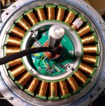
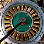
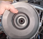
edit: images from own motor and the magnet ring from a youtube video sicne I forgot to image it. Yes the hall sensors are unprotected but I'm going to change out the pcb's with the final revision anyway so I'm not too worried.

IMG_20240131_190626.jpgIMG_20240131_195553.jpg1706734087033.png
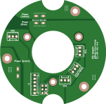
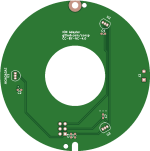
PCBs to fix the missing halls etc, ignore all the "test" pins and the wonky traces since it was a bit of a rush job. I just use a board-to-board connector (you can see where I manufactured the prototypes :LOL:), I'll make them available online for anyone to use if someone want to rebuild one of those motors (after a made sure they align properly, edit: they don't but close enough for testing), the "colors" are incorrect and was my best guess at the time, I also took the wrong footprints for the sensors so the halls are reversed (no worries, the software can correct for this):
bottompcb.pnguppcb.png

Two pcb's is since the wires come out below the sensor ring and there is a gap of about 2cm between them.
I got the info from a Dutch forum the ring is never aligned and you need to figure out the offset as they normally do that at-factory. I first thought they would use a different configuration to screw with me but it turns out it's just 20 poles like the normal magnets. so it should be 120 degree "compatible". It technically a PMSM motor but works fine with the OS software and the difference at 250-300w is not enough to care about (except for zero-start capability if you have no hall sensors). Since it's a munual job you need to make sure the hall sensors align as "twisting" them can create an offset. For the final version I'm goign to 3d print a retaining bracket to keep it in position.

The 0603 pads are there for placing small caps to get rid of the noise, but it turns out they are not needed (yet).

The actual signal lines would have to be disconnected from the rest of the controller, and active or passive electronics to buffer and rescale that to what the controller MCU inputs can take.
I figured as much, even better to isolate the stuff then with optoisolators and get a separate power curcuit. That makes sure the opto's die before anything else. But I'd only do that with a more expensive controller since replacing this one is cheap enough. Looking at the money I threw at it, I could almost buy half a working bike (yes I'm not kidding, they sell working ebikes for an insane amount).

Do you have anything else with a powered wheel? Put the tires against each other and use the one to spin the other. ;)
The drill idea came to mind. Eventually went with "manual excitation" and if you take the median of the results you pretty much end up where you should be. I tried doing the arrival times calculations since you got to use what you were tought some day and when I was doing it I realised it would end up in a bell curve anyway since all the tail results would have to be ignored (as long as you get enough measurements!!!! More measurements == more better). I went with the "do it over uart and do the processing elsewhere" method as it's accurate enough (since we can only align to 360/255th degree anyway with the OS software. The delta correction is off though by about 60-70 degrees so there is work to do there. I'm not ruling out I made a mistake somewhere since it is consistent.

On topic:

There is still some "7" result (e.g. all halls deactivated and high) which is odd but it only happens when the engine is spinning down in zero-dc mode (for measuring the delta angle). Haven't tried it under any load over 2 amps (at 32v) since my psu will go into current limiting mode otherwise so we will have to see when I put it on the bike. Also I'm afraid my bench will destroy itself if I run it that fast. It runs without noise and at about 200-300mA@32V will spin fine at about 6kp/h which I guess is low enough to be in the ballpark of good. It can also overcome friction and self-start without a push, which is nice to have.

edit2: pcb's arived, mounted the pcb's and redid the angle calculations and works fine again. so far it's workign great. Noise is a bit less without all the testing equipment but still there (drops to near ground at ~100ns timing) but I have not noticed any weird errors. I'm still concerned that the sensor signals drop that much but if the MCU doesn't care I don't either.
 
Last edited:
EDIT: first time around I missed some of your reply somehow, so you can ignore the below. I'm leaving it for other readers that come along that might not know how these things work, and what they could do to use such a motor.

Originally there is a custom hall board but since it uses 6 linear halls at 38ish degrees offset it's probably for a scheme you describe.
If that's the case, and the magnet ring you're using is the original, then it's going to be magnetized with a continuously-varying field, and not alternating poles matching the rotor magnets.

That means that using the typical ABC/UVW-matching 3-digital halls won't correctly read this ring to give you rotor position the way the controller is expecting.

You'd either have to
--replace the ring with one that is magnetized to match the rotor magnets, and is positioned to line up with them,
--or remagnetize the ring you already have,
--or use an MCU of some type between the halls and the controller to translate the output.

Otherwise you won't get the correct hall sequencing.

If you do get the correct sequencing, reliably, then it's already magnetized the correct way; then you just have to be sure it's lined up with the actual rotor magnets correctly (so the cover it's on must be installed exactly correctly each time), or else use an MCU of some type between halls and controller to correct the advance or retard of the timing (like Burtie's Timing Adjuster did).
 
Last edited:
Yea I was wondering about the reply, but it's definetly not a varying field, it's periodic all the way, up to my accuracy manualy running a sensor by the ring and not crossing the wires to confuse myself. The "angle" might also be 36 degrees which would be ok for the engine (24 coils, 20 pole) but I have no accurate angle measuring device and I took the data from somewhere else (as in, assumed someone measured the angle correctlyish). Try measuring at 1 degree angles with your ancient highschool protractor.

About timing: I did a few calculations and the deviation after about 1000 measurements (keep spinning for about a minute to be sure) should be less than the minimum (360/255). Unless you time your manual spins -exactly- (and I mean exactly) so the heaviest slowdown (or speedup) is most during one specific 60 degree part. Humans create too much noise so this should never happen. And it's been running fine now. I'm going to make some new pcb's and order them (with a 48 degree separation instead of 120, the 120 angle was a safe bet) and add a 3d printed "hall sensor retaining ring" to make sure everything stays in place under bumpy-road stress. We have a nice belgian-style cobble road a few km away which will be my final test after I reassemble the bike -topgear testing style-.


On topic:

I replaced one FET (one of the non ST ones, the CRST041N08N) and there is less of a drop (it varies a bit per sensor but all less), not much but at least a bit (ballpark is 10ns less rise time on one of the halls before returning to 5V on the output). It won't affect operation since it was working OK now but there is definetly some issue somewhere.
 
Last edited:
Back
Top