You are using an out of date browser. It may not display this or other websites correctly.
You should upgrade or use an alternative browser.
You should upgrade or use an alternative browser.
Rectifier Huawei R4850G2 48V 42~58V 3000w
- Thread starter vicens
- Start date
analog8484
100 µW
- Joined
- Mar 4, 2019
- Messages
- 9
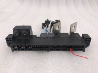
TIOK said:When you insert the connector, pin "6" closes to the negative output, and the unit starts.Does the contact "6" control output enable/disable?
If you don't need it, you can cut off the track coming from the contact, in the place indicated by the arrow on my photo. And start the unit as before, closing contact 10 on a common wire. And you don't need to glue anything.
Thanks. For temporary testing, I had only Kapton tape on the bottom covering contact "6" so the pre-charge contacts on the top remain accessible. The result is that the in-rush spark appears to be less when connecting to battery without first powering on the R4850g2 *and* the output does not get enabled automatically. This is almost perfect.
I am charging a server rack battery that has pre-charge output so the issue now is that battery appears to repeatedly pre-charge/discharge the R4850g2 output capacitors at low current (~0.1A) when the R4850g2 output is physically connected but not powered even with contact "10" disconnected. This means the battery will slowly get drained when R4850g2 is physically connected which is not acceptable. It's a very strange behavior.
celioregoli
100 µW
- Joined
- Oct 22, 2017
- Messages
- 9
I just bought a huawei R24050G1 270V 50A 15Kw on taobao and it is very similar to the R4850G1, because it only has on off and can bus. I bought it with my eyes closed, because I can use it immediately to charge my car batteries and then disconnect it with the bms, at 225v, but in the future I'd like to control the voltage with the can bus. i wonder if the potentiometer for the R4850G1 can work on the R24050G1 . And maybe with the same can bus commands. I can't find any documentation on the web. how could I do? if the commands are different, can I sniff in some way, with patience with the PC?
On the Eltek Flatpack the commnds are the same between 24V 48V 120V 220V and 380VDC versions. They only have different multiplication factors 10 or 100 in the dezimal to hex conversion.
Megmeet also uses the same commands for the 24V 48V and 60/72V Modell and they use the same pinout and connectors like Huawei.
I would just try it with the huawei , perhaps with different multiplication factors for voltage and current.
Veriv uses floating point to hex conversion.
Megmeet also uses the same commands for the 24V 48V and 60/72V Modell and they use the same pinout and connectors like Huawei.
I would just try it with the huawei , perhaps with different multiplication factors for voltage and current.
Veriv uses floating point to hex conversion.
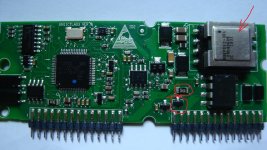
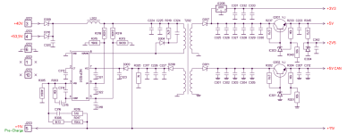
These units are designed for round-the-clock operation, without shutting down. The battery is discharged, not the capacitors, but the dc/dc converter on the control board. The voltage from the output is supplied to it in parallel with the standby voltage through a diode. It is possible to remove the diode, but you are unlikely to be able to do it.I am charging a server rack battery that has pre-charge output so the issue now is that battery appears to repeatedly pre-charge/discharge the R4850g2 output capacitors at low current (~0.1A) when the R4850g2 output is physically connected but not powered even with contact "10" disconnected. This means the battery will slowly get drained when R4850g2 is physically connected which is not acceptable. It's a very strange behavior.
spherezero
1 µW
- Joined
- Dec 14, 2022
- Messages
- 2
rigmo said:3. The module resets and restarts.
If the power module is shut down in case of failure, in any mode, press and hold the button for more than 6 seconds, the red/blue light flashes at the same time, and the power module resets and restarts.
4. Under voltage to turn off the power, (this function can be selected to turn off or on)
If the power supply encounters a fault or has a heavy load and the output voltage drops to less than 36V, the power output is turned off for 5 seconds. After the problem is removed, the power module is powered off and restarted, or the button is held down for more than 6 seconds.
5. The battery is fully delayed to turn off the power module output (you can choose to turn off this function, no delay shutdown)
When the battery is fully charged, the current starts when the current drops to 0.3A, and the power module output is turned off after the time is reached. (Delay time is 1 minute to 240 minutes optional) After the power module is powered off, it can be restarted, or the button can be reset for more than 6 seconds.
Has someone tried to sniff the CAN Reset Command for the R4850G2 from the Poti-CAN Controller Board ? From the description it seems to be possible.
spherezero
1 µW
- Joined
- Dec 14, 2022
- Messages
- 2
dr_lulz said:in case anyone cares, this is how my PSU looks now:
i soldered 8mm bolts for battery and attached screw terminals for 2.5mm^2 230v cables.
Hopefully enough for 70A for several hours
The 230V Connector looks very well !
analog8484
100 µW
- Joined
- Mar 4, 2019
- Messages
- 9
TIOK said:These units are designed for round-the-clock operation, without shutting down. The battery is discharged, not the capacitors, but the dc/dc converter on the control board. The voltage from the output is supplied to it in parallel with the standby voltage through a diode. It is possible to remove the diode, but you are unlikely to be able to do it.I am charging a server rack battery that has pre-charge output so the issue now is that battery appears to repeatedly pre-charge/discharge the R4850g2 output capacitors at low current (~0.1A) when the R4850g2 output is physically connected but not powered even with contact "10" disconnected. This means the battery will slowly get drained when R4850g2 is physically connected which is not acceptable. It's a very strange behavior.
8.JPG
54.png
That makes sense ... thanks! For clarity, is the diode you circled D310 on the schematic? The diode doesn't look too hard to remove with a hot air gun assuming the module is not too hard to access. However, would removing the diode cause DC-DC converter output disruption in some situations?
celioregoli
100 µW
- Joined
- Oct 22, 2017
- Messages
- 9
hwckent said:Mr.: Huawei R24050G1 plus Bluetooth control module is more suitable for your needs.celioregoli said:has anyone understand out how to raise the maximum voltage? I need 75v
this is my electric 106 project.
https://photos.app.goo.gl/7Ph1hQFYyCydSPNZ9
I want to make a three-phase charger to connect to the 22kw columns. I want to use 6 huawei rectifier. I would like to change them to 75v to put 3 in series and make 225v. And three more in parallel to have double the current. When I find a 11kw column with orion2 bms with the canbus it lowers the current. I just have to understand the modification to get 75v.
Or I could connect 6 , 41v rectifier in series and do the 246v and with some diodes in series I lower the voltage due to the drop of 0.7v for each diode, there are 12, I put 24. what do you recommend?
IMG_20211106_004135.jpg
Huawei R24050G1 is a high-efficiency, high-power density AC-DC rectifier module that supports three-phase voltage input from 260V AC to 530V AC, a rated output of 270V DC, and an output power of 15kW. The rectifier module adopts an isolated CAN communication interface, and the communication with the monitoring module adopts the CAN communication protocol. Through the monitoring module, the rectifier module can realize functions such as voltage regulation, current limiting, and single-module switching.
? Efficiency ≥ 97%
? Input voltage range 260~530Vac
? Operating temperature range -10~65°C
? Total harmonic distortion (THD) ≤ 5%
? Support hot swap function
? Fully digital control
? Support CAN bus communication function
? Support voltage regulation, current limiting, current sharing functions
? Meet RoHS requirements
? Obtained TUV, CE and Thiel certification
Product category R24050G1
Basic index
Size 206mm (width), 470mm (depth), 83mm (height)
Weight ≤12kg
Cooling mode: built-in fan, wind out after forward wind
Input characteristics
Input voltage 260~530 Vac
Rated voltage 380Vac / 480Vac
Input frequency 40~70Hz, rated value: 50Hz/60Hz
Rated input current ≤33A
Power factor ≥0.99 (25°C, full load)
THD ≤ 5% (50%-100% load)
Output characteristics
Output voltage 200 – 290 Vdc, rated value: 270 Vdc
Output Power
15kW(304 Vac~530Vac); 7.5~15kW(260Vac~304Vac linear derating)
Environmental indicators
Working temperature -10°C~65°C
Storage temperature -40°C~75°C (without packaging)
Relative humidity 5%~95% (non-condensing)
Altitude change
≤4000m (the high temperature derating under the operating environment conditions when 3000~4000m is used, every 200m increase will reduce 1°C)
Protection characteristics
Input overvoltage protection 530~550 Vac
Input undervoltage protection ≤ 260 Vac
Output overvoltage protection
297.5-302.5 Vac (1. When the internal fault is overvoltage, the module is locked; 2. When the external output voltage is within the protection point, the module works normally)
Output short circuit protection
Long-term short-circuit, automatic recovery after the short-circuit disappears; after the short-circuit> 10s, the module performs short-circuit protection in a period of 16s
Over temperature protection ≥ 65°C start-up protection, ≤ 60°C self-recovery
Reliability index
MTBF 450,000 hours (T=40°C, rated input, full load output)
Noise index
≤ 55dB (T=25°C, phase voltage Vin=220 Vac or 230 Vac, full load output)
Thanks so much for the advice. I read it after a year. I just bought it for 300usd on taobao. shipping excluded, shipping is done by cssbuy.com
celioregoli
100 µW
- Joined
- Oct 22, 2017
- Messages
- 9
dominik h said:On the Eltek Flatpack the commnds are the same between 24V 48V 120V 220V and 380VDC versions. They only have different multiplication factors 10 or 100 in the dezimal to hex conversion.
Megmeet also uses the same commands for the 24V 48V and 60/72V Modell and they use the same pinout and connectors like Huawei.
I would just try it with the huawei , perhaps with different multiplication factors for voltage and current.
Veriv uses floating point to hex conversion.
Thanks, when it arrives, I'll try. I have one question left, I've read all the messages from the beginning, but it's not clear if with 2 in parallel, I can use the same can bus channel, do they conflict? Or with the same message, do they both do the same thing? because otherwise I would have to change the address and I haven't seen anything on how to do it.
The Chinese remove this diode when they redo the blocks at 90-120 Volts, and the block works without problems. There are 4 revisions of the R4850G2 blocks and the schematics are slightly different. In the photo on the board, in series with the diode, there is a resistance of 2R2. You can delete it.That makes sense ... thanks! For clarity, is the diode you circled D310 on the schematic? The diode doesn't look too hard to remove with a hot air gun assuming the module is not too hard to access. However, would removing the diode cause DC-DC converter output disruption in some situations?
I am very interested in the results when your R24050G2 arrives. I am using many R4850G2's for 48V batteries and for a High Voltage project I am building a 27kW 3 x 3 stack. First 3 x R4850G2 serial in a 1U rack powered by 3-phase 230/380VAC to charge a single 42S Li-NCM battery upto 175.5V. And second 3 x those 42S battery/charger combo's to get a total string of 126S and 526.5V.celioregoli said:Thanks so much for the advice. I read it after a year. I just bought it for 300usd on taobao. shipping excluded, shipping is done by cssbuy.com
That all looked pretty smart when I started but now I do worry a bit whether this all will work reliably with such high voltages, even with the intermediate 175.5V stage. The things I am still researching are:
- High Voltage isolation
- Can-bus isolation
- Can-bus signal separation between units <- this is about can-bus addressing foremost
- Software integration to act as a single can-bus controllable charger and presented as such to a master BMS
With respect to the can-bus addressing, I have several official Huawai controllers, an older one that occupies the 4th slot in the 1U rack and a newer one with it's own housing. I plan to do some reverse engineering on all the can-bus messaging going on with 3 units plus controller in a single rack hooked up to the external controller. I have a suspicion there is some address negotiation going on when these units start up, when I have some results I will report back here.
But meanwhile, learning about the mere existence of that R24050G2 unit started me on a bit of internet research and I quickly found that Huawai sells a R100030G1 unit that supplies 300V 100A upto 1000V 30A in a single 30kW unit. If I can get me one of those at a reasonable price I am good without all the added complexity.
I even found a few on taobao such as https://item.taobao.com/item.htm?spm=a230r.1.14.22.4fc625d1BgaBKQ&id=695448907203&ns=1&abbucket=10#detail
But my last order on taobao was a miserable experience, not taobao itself but the agent I used, parcelup.com, didn't live up to my expectations to say the least and the shipping cost (to NL) were way higher than I expected. Could you share a bit about your experience with your agent cssbuy,com and their cost structure especially for shipping?
Anyway, 1st post too, about time. Cheers
Attachments
You seem very well informed about these Huawai units, any chance you can help us find some official can-bus protocol information? That would be much appreciated.TIOK said:These units are designed for round-the-clock operation, without shutting down. The battery is discharged, not the capacitors, but the dc/dc converter on the control board. The voltage from the output is supplied to it in parallel with the standby voltage through a diode. It is possible to remove the diode, but you are unlikely to be able to do it.I am charging a server rack battery that has pre-charge output so the issue now is that battery appears to repeatedly pre-charge/discharge the R4850g2 output capacitors at low current (~0.1A) when the R4850g2 output is physically connected but not powered even with contact "10" disconnected. This means the battery will slowly get drained when R4850g2 is physically connected which is not acceptable. It's a very strange behavior.
8.JPG
54.png
I have no information on can.You seem very well informed about these Huawai units, any chance you can help us find some official can-bus protocol information? That would be much appreciated.
TIOK said:These units are designed for round-the-clock operation, without shutting down. The battery is discharged, not the capacitors, but the dc/dc converter on the control board. The voltage from the output is supplied to it in parallel with the standby voltage through a diode. It is possible to remove the diode, but you are unlikely to be able to do it.I am charging a server rack battery that has pre-charge output so the issue now is that battery appears to repeatedly pre-charge/discharge the R4850g2 output capacitors at low current (~0.1A) when the R4850g2 output is physically connected but not powered even with contact "10" disconnected. This means the battery will slowly get drained when R4850g2 is physically connected which is not acceptable. It's a very strange behavior.
8.JPG
54.png
Do you happen to know where the can-bus transceiver is located as well? And what is true about can-bus ground, _on the other end of the (can-)bus_, to be required to be connected to the PSU's DC- (or DC+ or GND for that matter, just not to float nor any GND elsewhere)
The CAN bus is just two wires, CAN - H and CAN - L. No more wires are needed.Do you happen to know where the can-bus transceiver is located as well? And what is true about can-bus ground, _on the other end of the (can-)bus_, to be required to be connected to the PSU's DC- (or DC+ or GND for that matter, just not to float nor any GND elsewhere)
celioregoli
100 µW
- Joined
- Oct 22, 2017
- Messages
- 9
the R24050G1 has arrived, I was able to buy it directly on taobao and have it sent to me by cssbuy. with 300 euros on taobao and 150 euros on cssbuy with DHL it arrived in 1 week. Now I have a 15Kw 200-270vdc charger. It works perfectly with the commands of the little brother r4850g2, the 220v voltage takes it correctly and obviously at 50v give error. In the past I had thought of putting the 4850 outputs in series, but I think this is the best solution for high voltages. I found these R75020G1 R50030G1 R33640G1 R24050G1, the r24050 comes up to 270vdc. Then this did a great job based on botox esp32, made linux commands.I am very interested in the results when your R24050G2 arrives. I am using many R4850G2's for 48V batteries and for a High Voltage project I am building a 27kW 3 x 3 stack. First 3 x R4850G2 serial in a 1U rack powered by 3-phase 230/380VAC to charge a single 42S Li-NCM battery upto 175.5V. And second 3 x those 42S battery/charger combo's to get a total string of 126S and 526.5V.
Review: Huawei R4850G2 Power Supply 53.5VDC, 3kW with CAN – Beyondlogic
With my orion2 bms I can control it and set the maximum voltage and I'm working to control the current with the bms. At this point it remains for me to discover 2 commands that I would need, assign a different address to use 2 with the outputs in parallel, and be able to change the canbus baud from 125,000 to 500,000 kbps.
I thought, since huawei has a certain logic, namely that if i give a command, even the wrong one, to the right address, he replies, and so i can try to send a series of commands to see if he then replies. but is hard.
I hope your work on the can bus gives results.
as for how to buy on taobao, ask me, I can help you, I note that it was very difficult to register in Chinese, luckily there is google translate which also works with camera images. and the android app, required, is only in Chinese.
I'm fine with the Chinese app because it's structured the same as my aliexpress app and going by heart, I click right without knowing how to read Chinese.
I bought it here
Attachments
Last edited:
celioregoli
100 µW
- Joined
- Oct 22, 2017
- Messages
- 9
App Android Huawei and Torque.
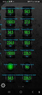
if it is of interest to anyone, I have just finished configuring torque and orion bms, and with great satisfaction the dialogue takes place perfectly between Huawei with the can bus on Orion which I connect with ELM327 with torque and with the PIDS that I created, and the dbc for orion that I created, everything works perfectly. I believe that instead of orion you can use Arduino and the Torque Control plugin.

 github.com
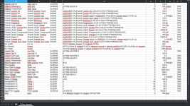
I attach the dbc file for orion and then the dash and csv for torque
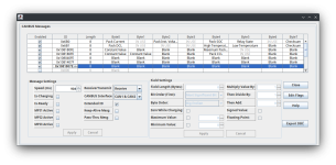
For the success of this work I have to thank botox for the code, the site beyondlogic for the tables, and Andrew of Ewert Energie , Orion2 BMS.
I racked my brain creating the csv function for torque.

if it is of interest to anyone, I have just finished configuring torque and orion bms, and with great satisfaction the dialogue takes place perfectly between Huawei with the can bus on Orion which I connect with ELM327 with torque and with the PIDS that I created, and the dbc for orion that I created, everything works perfectly. I believe that instead of orion you can use Arduino and the Torque Control plugin.
GitHub - piemmm/torque-arduino: A simple Arduino sketch that allows you to send data to Torque Pro for Android
A simple Arduino sketch that allows you to send data to Torque Pro for Android - piemmm/torque-arduino

I attach the dbc file for orion and then the dash and csv for torque

For the success of this work I have to thank botox for the code, the site beyondlogic for the tables, and Andrew of Ewert Energie , Orion2 BMS.
I racked my brain creating the csv function for torque.
Attachments
Last edited:
celioregoli
100 µW
- Joined
- Oct 22, 2017
- Messages
- 9
Thanks.Very nice, but something is mixed.
Output power is higher than Input power
The parameters are indicative, I sent them on the canbus to test all the software and hardware mechanisms, because at home I don't have the 380v to power Huawei, I had tested Huawei in the past, and in theory, when I connect it, everything works. I have just finished the software part and in these days I will do the real test.
I have a 4850g 0-90v (real was 0-100v I think and 0-32,5A) 3000 charger. Used a little for 95v battery but now 75v battery or 18s.
The other day my 40A fuse melted and blow. Lucky. Yes. It did its jobb.
I was sad but tried to connect output to get charge without fuse so charged 80-90%. Allthough the next day as I wanted to trickle the rest of the charge to fully AC positive or negative shorted to mosfet input side I think and charger turned of me thinking it was really dead. It can't survive two events.
Got it working a few hours later and home again the auto-fuse had tripped which was the one my charger was using.
So now I am fixing it real good before I will use it again.
Dominik H. What has happened to your 3000w charger? Your photos of your 0-90v charger was different from mine. Maybe I had a better version?
In general I also like to see IF these Huaweis can be modded more easely without any other modification but physical and also with the ability to change voltage and amps. ( I get one can series the output connetions on these unmodded or soft modded PSUs. I should really go lock at some photos. I have never series any charger with another charger before)
The 4850 and smaller 30 someone asked can be used with some items and be made to work with a higher voltage up to about 58v but I didn't get an answer if any programming work was needed for that mod. (source: some youtube video )
celioregoli
100 µW
- Joined
- Oct 22, 2017
- Messages
- 9
Similar threads
- Replies
- 4
- Views
- 1,709
- Replies
- 1
- Views
- 906
- Replies
- 11
- Views
- 2,064


