
-
Hello ES! We could use some help to get us past the finish line on building the new knowledgebase for the forum.
Can you donate? Please see our fundraising page. Thank you!
You are using an out of date browser. It may not display this or other websites correctly.
You should upgrade or use an alternative browser.
You should upgrade or use an alternative browser.
Rectifier Huawei R4850G2 48V 42~58V 3000w
- Thread starter vicens
- Start date
The rectifier sends a lot informations via can bus and it also sends alarm codes if you ask for them.
I have a complete can protocoll from a Huawei compatible rectifier. I think most of the codes will work for the Huawei, but I have not checked it, as I had no need for alarm codes and no time to test things I do not need.
I have a complete can protocoll from a Huawei compatible rectifier. I think most of the codes will work for the Huawei, but I have not checked it, as I had no need for alarm codes and no time to test things I do not need.
Last edited:
tosa8
New here
I verified what dominik has posted about addressing individual R4875G1 units. In my application, each R4875 is connected to its own load, and I wanted to be able to adjust the output voltage of each supply on a common CAN bus. When I had 3 units powered up, they went to the default voltage and the yellow LED's were blinking. When one unit was command to a different voltage, all of the yellow LED's stopped blinking, and one of the units went to the commanded voltage. It seems that the addresses are somehow decided amongst themselves, but it is not repeatable between power cycles. I monitor the voltage output of each unit, and I can use that information to find out which unit has which address by slightly changing the commanded voltage.
Thanks to all on this thread for the valuable information about the Huawei supplies - the support here is really amazing.
Thanks to all on this thread for the valuable information about the Huawei supplies - the support here is really amazing.
I have been trying to talk with my r4875g1 and it wont reply back with the info or if I try to send a command to change the voltage for example it wont react at all. Could it be I mixed something up, I used a termination resistor. Since I am receiving messages it should be fine? What can I start checking to help my find what the issue is.
Attachments
Can you share the document?The rectifier sends a lot informations via can bus and it also sends alarm codes if you ask for them.
I have a complete can protocoll from a Huawei compatible rectifier. I think most of the codes will work for the Huawei, but I have not checked it, as I had no need for alarm codes and no time to test things I do not need.
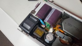
How do you connect the SMU02B to the recitifier?I have SMU02B. There are no fan settings in it.
You can only see the temperature of each unit.
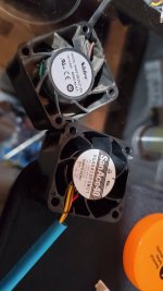
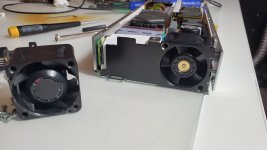
I tried this fan and it did not like it one bit. I connected it the same way with the sense and control wire in the same position but I guess it's expecting a different sense signal. Right away full speed even louder then original, voltage still outputting fine but red light flashing. I'm not sure if I should just return the fan or keep it and add a resistor in line to slow it down. If I use the old fan then i'm still going to get the same flashing red light when I add a resistor to it most likely.
Attachments
Last edited:
Best guess is the tachometer is being monitored and when it runs slow the red light flashes to tell you there's a fan problem.
If you don't need the cooling the fan provides at it's full speed, you could install a pulse doubler (or greater) that creates two pulses for every tach pulse that comes in. Then if the PSU is controlling the fan speed (presumably via controlling it's input voltage) it can turn the speed down on it's own.
If it doesn't do it on it's own you can then use the resistor to reduce it's speed.
Pulse doublers, or frequency doublers, can be made in a number of ways. A quick google finds this useful thread
Thank you for your input. Pulse doubler might come in really handy. In this case it doesn't seem to care about the rpm too much as long as it sees it spinning. I figured out what the issue is. The standard seems to be blue wire for control and yellow wire for sense, with the yellow wire beside v+. That's what I saw on Nidecs website when checking a very similar fan model and on google. In reality they used the yellow wire beside v+ for control and brown wire for sense.. It works now but I also had to use a resistor because even the much slower fan is loud and with a resistor it's tolerable. The issue isn't the decibels but the frequency of the sound, a normal computer fan will have low frequency sound so even at higher db its much more comfortable. Nobody that sees this try to place a resistor on the original fan, it needs a 1.5w resistor at least or the resistor will turn red hot and melt the surrounding wires.Best guess is the tachometer is being monitored and when it runs slow the red light flashes to tell you there's a fan problem.
If you don't need the cooling the fan provides at it's full speed, you could install a pulse doubler (or greater) that creates two pulses for every tach pulse that comes in. Then if the PSU is controlling the fan speed (presumably via controlling it's input voltage) it can turn the speed down on it's own.
If it doesn't do it on it's own you can then use the resistor to reduce it's speed.
Pulse doublers, or frequency doublers, can be made in a number of ways. A quick google finds this useful thread
Attachments
If you want to move the same amount of air with a LOT less noise, and at a much lower frequency, remove the small fan entirely and make an adapter duct from the small fan mounting point to a 5" or bigger fan, with at least a few inches between the ends of the duct. (the shorter it is, the noisier, and the higher frequency the noise will probably be).
A quick google didn't find a fan reducer or adapter duct commercially available for this situation (where the air will need to come from the corner of the duct, so the new fan still "fits" the outline of the PSU (except for being taller)), but one could be 3D printed easily enough. There are probably designs already out there on the free 3D parts databases that could be modified.
A quick test version could easily be done with some cardboard and tape.")
If you don't want the fan to respond to the PSU at all and only run at a fixed speed, you could leave the control wire disconnected, and use a fan that has a tachometer of the right type of output but doesn't require a control line, and already runs at the right RPM. Or use a fan with a variable voltage control line and a potentiometer for that (rather than the probably-PWM control the ones you're using now have) to alter the speed until it works as desired. Then you don't need a resistor in the fan voltage supply line that wastes all that power as heat.
BTW, there are different kinds of tach as well as control signals--some tachs are PWM output, some are analog voltage, etc.
A quick google didn't find a fan reducer or adapter duct commercially available for this situation (where the air will need to come from the corner of the duct, so the new fan still "fits" the outline of the PSU (except for being taller)), but one could be 3D printed easily enough. There are probably designs already out there on the free 3D parts databases that could be modified.
A quick test version could easily be done with some cardboard and tape.
If you don't want the fan to respond to the PSU at all and only run at a fixed speed, you could leave the control wire disconnected, and use a fan that has a tachometer of the right type of output but doesn't require a control line, and already runs at the right RPM. Or use a fan with a variable voltage control line and a potentiometer for that (rather than the probably-PWM control the ones you're using now have) to alter the speed until it works as desired. Then you don't need a resistor in the fan voltage supply line that wastes all that power as heat.
BTW, there are different kinds of tach as well as control signals--some tachs are PWM output, some are analog voltage, etc.
That should work too. They're also called squirrel-cage, or centrifugal blower, when shopping around.
Are you willing to share you (compatible) protocoll documentation?The rectifier sends a lot informations via can bus and it also sends alarm codes if you ask for them.
I have a complete can protocoll from a Huawei compatible rectifier. I think most of the codes will work for the Huawei, but I have not checked it, as I had no need for alarm codes and no time to test things I do not need.
The Input current limit and on off parameter I can not find any where.
Would love to see that as well! Just got hands on 4850G2 and having issues for some reason, maybe someone can give a hint?
I boot it with both sense pins connected to ground. The unit boots well, no red/yellow lights and I’m able to communicate with it over can. Able to read data as well as request voltages. The issue I’m having is this:
1) I request 55v with byte[1] being 0 and get instantly to the 55v output. -all good
2) I request 55v with that byte being 1, and of course no change. I unplug power from the ps, wait 30 seconds and power it back on. Still, bolt voltage is like 48v or something around there. -that’s not what I expected.
3) I do the same command as I did on number 2, though let’s say set it to 53v, but this time abort all communications with the PS for 60 seconds. (Don’t send any more messages). The yellow light starts to blink indicating PS went offline mode and Voltage drops down to 53v. Thats expected and correct. I reboot the PS, and voltage is back to damn 48v!
Also, just with fresh boot, only command being sent is to request data every 10 seconds, my fan is spinning on max with idle AC draw of 23watts! Is there any way to use can to put this unit offline until I need it?
From my experience having multiple psu's on the same can bus and the outputs connected in parallel resets the so called "offline mode" after a power loss. After setting a certain voltage or current during operation and writing it to their internal rom (trough canbus) they keep their preset voltage or current, etc. until they are power cycled. That means that all the psu's jump back to their default preset, which is about 54ish volts, aswell as no current limit. I think that this must be a safety feauture by huawei because when one psu for example has a fault on the canbus and is therefor set to a different voltage than the others, a voltage overshoot or even a high curtrentflow between the units can be prevented. Not sure about this tho. Still, just a quick can message after the reboot will set all the units back to the original parameters as desired. Furtmore there is the following command which allows to send ONE or Multiple psu's to sleep. The ID of the frame: 0x108080FE (all psu's on the can bus) or, 0x108180FE for PSU1, 0x108280FE for PSU2, 0x108380FE for PSU3 and so on. Finally the actual Data of the can Frame: send following for to turn ON: 01 32 00 00 00 00 00 00, aswell as the following to turn OFF: 01 32 00 01 00 00 00 00.Would love to see that as well! Just got hands on 4850G2 and having issues for some reason, maybe someone can give a hint?
I boot it with both sense pins connected to ground. The unit boots well, no red/yellow lights and I’m able to communicate with it over can. Able to read data as well as request voltages. The issue I’m having is this:
1) I request 55v with byte[1] being 0 and get instantly to the 55v output. -all good
2) I request 55v with that byte being 1, and of course no change. I unplug power from the ps, wait 30 seconds and power it back on. Still, bolt voltage is like 48v or something around there. -that’s not what I expected.
3) I do the same command as I did on number 2, though let’s say set it to 53v, but this time abort all communications with the PS for 60 seconds. (Don’t send any more messages). The yellow light starts to blink indicating PS went offline mode and Voltage drops down to 53v. Thats expected and correct. I reboot the PS, and voltage is back to damn 48v!
Also, just with fresh boot, only command being sent is to request data every 10 seconds, my fan is spinning on max with idle AC draw of 23watts! Is there any way to use can to put this unit offline until I need it?
Greetings
Julian
Last edited:
In general its important to send the correct frames when working with multiple psu's. To know which unit you are talking to.
-0x108080FE (master frame, will talk to every device on the canbus)
-0x108180FE (will only talk to psu 1)
--> the psu's get their respective address from the order they are starting at /are vailable on the canbus. This can be a matter of seconds and is therefor hard to control. Furthermore there is no real way, as far as i know, to set a certain address for an individual psu and maybe even hardcode it into it's respective internal rom.
-0x108280FE (will only talk to psu 2)
-0x108380FE (will only talk to psu 3)
.....
When working with multiple psu's you should always talk to them using the master frame.
Last edited:
The following should help you out.Are you willing to share you (compatible) protocoll documentation?
The Input current limit and on off parameter I can not find any where.
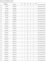
GitHub - craigpeacock/Huawei_R4850G2_CAN: Example code to communicate with Huawei R4850G2 Power Supply via CAN
Example code to communicate with Huawei R4850G2 Power Supply via CAN - craigpeacock/Huawei_R4850G2_CAN
 github.com
On his github there is a table with the listed commands and the can frames/ values.
one page backAre you willing to share you (compatible) protocoll documentation?
The Input current limit and on off parameter I can not find any where.
Yep already tried that command. Sending 0x01 3rd byte turns off the fan and cuts output, but unit is still pulling over 25watts. So not sure if there is a way to actually truelly put it to sleepFrom my experience having multiple psu's on the same can bus and the outputs connected in parallel resets the so called "offline mode" after a power loss. After setting a certain voltage or current during operation and writing it to their internal rom (trough canbus) they keep their preset voltage or current, etc. until they are power cycled. That means that all the psu's jump back to their default preset, which is about 54ish volts, aswell as no current limit. I think that this must be a safety feauture by huawei because when one psu for example has a fault on the canbus and is therefor set to a different voltage than the others, a voltage overshoot or even a high curtrentflow between the units can be prevented. Not sure about this tho. Still, just a quick can message after the reboot will set all the units back to the original parameters as desired. Furtmore there is the following command which allows to send ONE or Multiple psu's to sleep. The ID of the frame: 0x108080FE (all psu's on the can bus) or, 0x108180FE for PSU1, 0x108280FE for PSU2, 0x108380FE for PSU3 and so on. Finally the actual Data of the can Frame: send following for to turn ON: 01 32 00 00 00 00 00 00, aswell as the following to turn OFF: 01 32 00 01 00 00 00 00.
Greetings
Julian
Yeah that is a little above my knowledge. Yes output is 0, but energy is going somewhere. I looked at the temperature data and when set to power off mode using that command, I do see both intake and exhaust temperatures raise slightly. Also I can hear electrical noise come from the supply, so my assumption is that it just cures output and fan, but energy is still being used and converted to heat clearly, which seems to be much more then 7w. Again, could be wrong but that was just my observation.25w apperent power.
Power factor at 230Vac is <0.1 at 0W output power.
<7W standby power at sleep mode
Probably it has more losses at 110-120V. I never tested with lower mains.
To have lower losses it would need to have a separate small standby power supply, butcI have not seen a telecom rectifier which has a standby psu.
To have lower losses it would need to have a separate small standby power supply, butcI have not seen a telecom rectifier which has a standby psu.
Hello,
I just purchased a Huawei R4850G2 for powering up an RF Amplifier. Question: After applying AC Mains power, To get supply to start you need to ground* both wires on the Start Plug? Is that correct?
* by ground I mean connect to 48 (-) pin
Thanks
Dan
Callsign: W6DKW
I just purchased a Huawei R4850G2 for powering up an RF Amplifier. Question: After applying AC Mains power, To get supply to start you need to ground* both wires on the Start Plug? Is that correct?
* by ground I mean connect to 48 (-) pin
Thanks
Dan
Callsign: W6DKW

Similar threads
- Replies
- 1
- Views
- 1,083
- Replies
- 1
- Views
- 1,442
- Replies
- 0
- Views
- 981
- Replies
- 1
- Views
- 1,298