Rectifier Huawei R4850G2 48V 42~58V 3000w

Depends on your plug. probably you have a different version.
I had four versions plugs until today and all worked with the black wire from start. The plug next to it is CAN.
The fourth not on my picture has 3 more wire pairs on the right side.

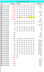
CANID HEX10 80 80 FEbroadcast to all rectifiers
Data01 00 00 00 00 00 xx yyonline voltage
Data01 01 00 00 00 00 xx yyoffline voltage
Data01 02 00 00 00 00 xx yyovervoltage Protection
Data01 03 00 00 00 00 xx yyonline current
Data01 04 00 00 00 00 xx yyoffline current
125KB/s

Permanent set (offline voltage) 56V permanent Data 01 01 00 00 00 00 E0 00 probably the PSU overshoots by 0,3V so try DE EC or anything in between. Changes will show up after 30 seconds.

If you want to see the changes immidiatly (online voltage) 01 00 00 00 00 00 E0 00 , but they will get lost after 30 seconds or after a new start..
 
I haven't been able to figure out how to change the current to desired amount. Looking at craigpeacocks github issues someone brought up that the number is in percentage of max current. Is the max current the same as what the unit is rated for max on the data sheet or is it depending on the input voltage? I am on 120vac so for me the max I set should be 2.3% If I want 32 amps or does it need to be for the 120vac 1600w spec which would mean the max current is already 33amps and I would just set the max current to 100% in that case. Which would be 768 converted to hex 0300.
"
For R4875G1
75A / 100 * value * 10.24"

This german guy seems to have it all figured out but doesn't share code.
 
The value is the same as for the R4850 and then the R4875 produces the same current. When you add the connection to get 4kw from the r4875, then it makes 33% more current with the same settings. But I do not know if there is a different value for 120V input, as I am on 230V mains.
I have 20 as multiplication value, and then it has to be converted to hex.
To get 30A out of the R4850
30x20=600 = 258 in hex
And with the right connections on the R4875 you will then get 40A, without the 4kW bridge you will get 30A with the same data.
 
Hello! I adapted the protocol for my R4875G2 and added new commands that I was able to discover. See attachment.
 

Attachments

  • Protocol_R4875g.xlsx
    13 KB · Views: 107
Hello! I have a R4850G2, but I have a problem with it. The device show wrong values for output current:
Voltage is set to 53.5V, thats ok. I take about 4A from the PSU in real, but the CAN send 35A actual current.
If I take more than 10A in real, the PSU says <60A and drop the voltage down. The values for current, send via CAN, are completly wrong.
Any ideas whats the problem with this device ? How they measure the current, with a shunt ?
I'm on 230V , bridge the slot detection 1& 2 to ground/-48V.
PSU starts too without CAN communication with the correct settings. CAN bus read and write ok too (using an Arduino Nano with MCP2515). Thats all works, but not the measure of the correct current inside the PSU.
 
Last edited:
Have you probably set an input current limit, this could force the psu to drop the output voltage.
Your Ampere readings over can should though be accurate.
 
My Post 283
expand...
Now I can answer my question myself.
If you send 0X01 09 00 01 00 00 20 00 the AC input current gets limited to 8A if you send 01 09 00 01 00 00 10 00 it gets limited to 4A, as you can see on the pictures. The electronic load would draw 60A , but the rectifiers limits to the set input current.
Factor for multiplikation is 1024 and than it hast to be hex converted.
To turn the limit off send 01 09 00 00.
Measuremenst are taken with 230VAC line voltage.
 
Hello everyone, I'm encountering an issue while trying to connect two R4850G1 in parallel. As per the datasheet, these PSUs should have a "current sharing" feature that enables them to distribute the load evenly. However, upon connecting them, I observe a minimum consumption difference of 7 amps between the two PSUs. I've also attempted connecting them using diodes, but the difference persists. I've reviewed previous posts on this forum but haven't found any mention of this specific issue. I appreciate any assistance you can provide.
 
Hello everyone, I'm encountering an issue while trying to connect two R4850G1 in parallel. As per the datasheet, these PSUs should have a "current sharing" feature that enables them to distribute the load evenly. However, upon connecting them, I observe a minimum consumption difference of 7 amps between the two PSUs. I've also attempted connecting them using diodes, but the difference persists. I've reviewed previous posts on this forum but haven't found any mention of this specific issue. I appreciate any assistance you can provide.
Hello! Connect the power supplies via CAN line. Don't forget to use a terminator in parallel with the CAN line (120 Ohm resistor)
 
Power supplies have a CAN bus. You need to connect the CAN of the first power supply to the CAN of the second power supply. A 120 ohm resistor must be installed between CAN-H and CAN-L. Refer to PDF documentation, power supply connector pinout, it describes the CAN bus pins.
 
Power supplies have a CAN bus. You need to connect the CAN of the first power supply to the CAN of the second power supply. A 120 ohm resistor must be installed between CAN-H and CAN-L. Refer to PDF documentation, power supply connector pinout, it describes the CAN bus pins.
Thank you for your response. I have already set the same voltage on both power supplies using a CAN adapter. Now you are saying that I only need to connect the two independent power supplies via the CAN bus and they will automatically recognize that they are in parallel? I don't need to send them any CAN messages for them to operate in parallel?
 
The value is the same as for the R4850 and then the R4875 produces the same current. When you add the connection to get 4kw from the r4875, then it makes 33% more current with the same settings. But I do not know if there is a different value for 120V input, as I am on 230V mains.
I have 20 as multiplication value, and then it has to be converted to hex.
To get 30A out of the R4850
30x20=600 = 258 in hex
And with the right connections on the R4875 you will then get 40A, without the 4kW bridge you will get 30A with the same data.
Something doesn't seem right. Im sending different current limits to it but nothing makes sense. I can see they apply and it saves them. If I try a really low value the voltage falls and doesn't rise even if I restart. If I set a slightly higher value the voltage goes to the set voltage and sets there but the current draw that im testing is too high and voltage doesn't fall. would you be able to try setting it to like 1amp and see how it goes. my testing method is a 10ohm resistor with a current clamp. the only thing I have been able to make it do is either 4.8amps or like some kind of weird oscillating current and voltage from like 0 to 700mA. I tried both 03 and 04. This is some values I tried, I also tried multiplying it by 20 or if I want 1 amp then setting it to 10 which is like 1.0, something from the excel sheet rybak27 shared. Maybe this thing doesn't work the way im expecting it to. I don't have variable load to test higher current values. I am trying to charge small battery packs and they will blow up if this thing pumps a unregulated amount of current. I want to limit the current to 1 amp and when i test it with the resistor I would expect the voltage to fall and the current to be 1 amp.1723846915311.png
 
Last edited:
I think you need 10% current from the max value to get stable operation.
I never tried to set it to 2A or 4A. Lowest I ever set was 10A.
Vertiv has written adjustable current 10-122% in their datasheet.
 
Last edited:
my testing method is a 10ohm resistor with a current clamp.
In order to get 1 Ampere at a load of 10 ohms, the unit must reduce the voltage to 10 Volts, and according to the passport it can only reach 42 Volts. Connect a load of 50 ohms, then the voltage, to keep the current at 1 Ampere, will drop to 50 Volts. Connect another 500 ohms in parallel, the voltage will drop to 45 Volts.
After connecting the load, the current does not immediately drop, but after a while.
 
Last edited:
hello everyone.
I am a new member. I have a power supply it is EPW50-48A. I have its pinout. It uses RS485 to control. Can anyone give me the control code of this type of device. I need to DIY it to use for solar charging.
 

Attachments

  • Pin detail.jpg
    Pin detail.jpg
    288.5 KB · Views: 20
  • Pin.jpg
    Pin.jpg
    118.8 KB · Views: 16
In order to get 1 Ampere at a load of 10 ohms, the unit must reduce the voltage to 10 Volts, and according to the passport it can only reach 42 Volts. Connect a load of 50 ohms, then the voltage, to keep the current at 1 Ampere, will drop to 50 Volts. Connect another 500 ohms in parallel, the voltage will drop to 45 Volts.
After connecting the load, the current does not immediately drop, but after a while.
I was expecting it to output 42v and then drop voltage to 10volts and output 1 amps when I connected 10ohms load. So it doesn't really work for this use case.
 
Has anyone tried higher voltage on these psus? I set it to 55v yesterday and it was getting a lot warmer then on 48v. Is that normal, Is it ok to run it at around 50c surface temp? I have it in an enclosed box to dampen the fan noise and at 48v it was basically room temp after running a few hours but at 55v it got quiet warm after a few hours.
 
Yes I had them also programmed to 57V for charging 14S liion batteries. They do it without any problem with 3kw output power.
If they ever get to hot they will reduce power.
If you need a quit power supply buy a fanless meanwell uhp and ad a big heat sink
 
Back
Top