Repairing Watts Up units

amberwolf

Administrator
Staff member
Joined
Aug 17, 2009
Messages
42,783
Location
Phoenix, AZ, USA, Earth, Sol, Local Bubble, Orion
file.php


Ianmcnally sent me a couple of malfunctioning WattsUp units in a recent care package
http://www.endless-sphere.com/forums/viewtopic.php?p=303752#p303752; one has a display problem
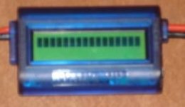
DSC03122 wattsup dead lcd.JPG
and the other only reads amps, not volts (or anything requiring volts to calculate)
View attachment 4

The latter was an easy determination as to the root cause:
View attachment 3
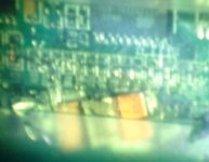
DSC03129 wattsup splatter thru case 2.JPG
but not so easy to troubleshoot. After prying the case open, I could more clearly see the problems:
View attachment 1
Cleaning up the solder was fairly easy, as most was just cold-stuck blobs not actually melted to anything. But a few bits, including on the MCU pins, were soldered on well enough to require the soldersucker. :( So those were shorted pretty good, where the other bits might not have even caused a short at all, depending on oxides and whatnot between the splatters and the components they landed on.

After removing it all, it didn't make a lick of difference to the problem. :( I started comparing resistors and whatnot between the two WU units, for actual readings across them. I found this one:
Wattsup open resistor.JPG
totally open. It's supposed to be around 15Kohm reading there, and the one to it's right, based on the other WU and the functional one AussieJester had sent me a while back.

I can't actually read the markings on there, as my eyes are just on the edge of needing bifocals; my regular glasses (to compensate for my nearsightedness when I am walking around and riding and such) won't let me focus that close, but I can't see that well even with really good light for the tiny markings now. Used to be able to read the tiny tiny decals that Tamiya and such put on the military models, where a 1/4" decal could have a paragraph of text in it that I could actually read. Not anymore. :( And I can't find the stupid magnifying glass I though I had in my toolkit.

So I just started poking around on some dead boards from stuff I saved that have lots of SMT resistors in that form factor, and eventually found one whose markings appear the same as this one (based on rough shape since I can't quite see it). After about 20 minutes of fiddling around with the tiny thing, I eventually got it soldered in, replacing the open one. (after removing about a zillion solder bridges I kept making--my hands jitter too much for this stuff!).

I got a voltage reading, but totally wrong, showing 4.32V for a 39V source (one of the 24V chargers with no pack connected). I unplugged it, checked for solder bridges, ohmed out things and came up with normal readings. Tried again, and this time it gets 48.3V. :? :( Flipped the power off on the charger, tried again, and again, and got different readings each time. There is something else wrong in there, probably in the MCU. :(

Oh, well, it's still got a good LCD, so I'll just transplant that over to the other one, right?
 
So I pry open the blue-case WU, and checked the connections on the LCD. Found some corrosion, but cleaning that did nothing to alleviate the problem. Either the MCU is sending wrong data, a PCB trace is bad on one of the two boards inside, or the LCD itself is dead.

Since I apparently have a donor LCD from the first one, I'll just swap it over and test the theory, right? It didn't work quite like that...I got exactly the same display problem with the "new" LCD. Dangit. So much for an easy fix.

I test the first LCD by putting it on the green-case WU. Same problem displaying only one line of all black blocks. Uh-oh...that means that the other LCD I just put on the blue WU is probably now damaged, too.

I swap it back over, and yep, now I have two bad LCDs. Dagnabbit! I probably killed it with either ESD or heat, although I had my ESD wristrap on and attached to ground, that doesn't stop all ESD, just helps a whole lot. Best guess is the heat from desoldering it, then resoldering it. :(


Ok, at least one of these two WU can give me spare parts to fix my Turnigy Watt Meter. :) Since it's likely that the green one with the solderblobs is actually a bad MCU, might as well use it for parts.
http://www.endless-sphere.com/forums/viewtopic.php?f=2&t=21267&start=0
 
No - the all black line is just showing the LCD is powered, but is not recieveing valid data - chances are the MCU is stuffed.

Do you have a multi-channel 'scope you can probe the LCD with? You can see the data lines strobing.
 
No multi-channel here (well, I have two two-channels, a Tektronix 531A and the storage version of the same scope, that I might be able to sync together, havent' tried yet).

The LCD *was* receiving data before I tried to fix them, even on the blue one that started out with the display problem, because if I held it just right I could see values flickering within the nearly-black squares, as if they were scrolling along the single line of characters really really fast. I didn't try to see if this is still the case with them now, though.

Realistically, it'd be better if it *is* the LCDs, because I probably have some displays around somewhere that have compatible LCDs in them, but no other ATTiny MCUs (or a way to program them with the right code).
 
if it might encourage you, The turnigy wattmeter that cost 29$ have a copy of the watt,s up meter.

i have 3 watt,s up meter and 2 turnigy in my lab .

I posted something about that fact.

In my case when they blow it's because of too high voltage on teh input making the LM2936 3.3v regulator or the fuse resistor to blow.

I bought a batch of the soic 8 pin IC and repaired mine a couple of time.

I posted high res pics of both board if you would use them...
Here is the schematic!!: :wink:


http://endless-sphere.com/forums/viewtopic.php?f=3&t=13607&hilit=turnigy+wattsup&start=135

Doc
 
THanks--yeah, I was thinking of those pics and posts when I was doing the repairs, and that's what helped me troubleshoot these plus my Turnigy (and actually fix the turnigy). :)

When I have time to get back to these, the schematic (whcih I'd forgotten about) will help more. :)
 
Possibly encouraging me to have another go at fixing these:
DSC03773.JPG
Two two-line LCDs with essentially the same formfactor and pin placment as the existing ones, but this time with extension cables already soldered in place, including 15-pin DB connectors close to the display. That is interesting because it means that I could
A) troubleshoot easier by swapping displays around, assuming these turn out compatible
B) move the whole shunt and MPU board elsewhere on the bike from the display (as someone else did on their scooter already).

They came from HP servers, the little status displays off the front of the cases, donated by a friend today along with some nice 12V and 48V fans.

I stll have to do some checking to make sure the pinout matches, based on the p/n's on these:
DSC03774.JPG
DSC03775.JPG
if I can find any data on them. Otherwise I'll just try it and see. Can't make these two much worse I think. :)
 
Virtually all text mode LCD displays use the same Hitachi (or compatible) controller. The connector pinouts are pretty much the same. They come in a 14 pin single row or dual row 2x7 configuration. A few (usually graphics units) have 16 pin headers.

There can be a difference in the pinouts near the ends of the connections that are for the backlight. Polarity and current limit resistors, EL or LED backlight, etc.

Also, some controllers have a different circuit for controlling the LCD bias/contrast supply. Some have built in bias generators, some use external generators, some have a contrast pot. Go through the data for some of the SparkFun and CrystalFontz displays to get feel for what is involved.
 
I'll check them out. FWIW, I also have a Vacuum Fluorescent Display I'd like to try, which *may* be the same control setup (it has it's own PSU board for 12V input). Should be a lot easier to read at night and still be readable in daytime with the right contrasty stuff over it on the "dashboard" if shaded from sunlight.
 
Usually VFD displays use a different type of controller that is not compatible with the standard LCD controller. Also, I doubt it will be readable in daylight. Also, they have a limited lifetime (but longer than your ass in the saddle)

Also, I have run into some incompatible Hitachi style LCD controllers. I replaced a bad display on a Tektronix arbitrary waveform generator with an OLED display module. Unfortunately, it did not seem to work... the display was black. But when I powered off the box, the display momentarily lit up with the most beautiful, high contrast yellow and black text display that you ever saw. Apparently there was some display enable command required by the new display that the Tek firmware did not send... major bummer... :cry:
 
Back
Top