Replacing Hub motor trouble.

Joined
Apr 25, 2023
Messages
29
Location
So cal
I hope you guys can help me, I'm lost. I have a heavily customized cruiser ebike and the last item I'm addressing has gone very wrong.

The short story.
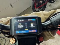
I needed to get a lower gear sprocket on the rear hub so I bought a Cassette style bafang motor with a cassette sprocket mount. Now that it's mounted and connected it's not running right. It has very low power and it chugs when below 7mph. I'm told my original motor was not a bafang as I thought. I'm hoping its that wiring colors are different than bafang codes are. The bike is a Kasen but I can't find any identifying info on the original motor. I don't mind replacing the controller if needed just so I know if it's the right one.
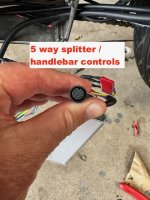
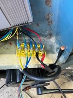
P.S. the two motors have different style screw lock connectors. I had to hard wire them still leaving the complete connector on the new motor. Cutting the quick connector off the controller side.
P.S. Both motors are a match power wise. 1000w. 48v

The longer story.
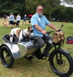
I bought the cruiser ebike and planned to add custom paint & home built sidecar to it. Styling it after WWll Indian motorcycle. But the final weight with the dog and my fat ass it could not climb the hills to get to my house. So I added a 1000w bafang mid-drive. A completely separate drive system. Left side of handlebars are the mid drive controls the right side has the hub drive. It's fast and capable now. The problem that put me where I am now is the chain. I kept breaking them. The offset between low gear and the 32T chainring mounted to the mid drive was too much. Jumping chain and braking links a lot. So I bought a Luna 42T offset chainring and needed to get at least a 42 T low gear rear sprocket. I bought a replacement hub motor with Cassette style sprocket connector. Cassette style gears have far better tooth selections. Now its much smoother shifting and running but I'm getting almost no power out of the hub motor.
 

Attachments

  • Lily 5.JPG
    Lily 5.JPG
    120.6 KB · Views: 22
3- My controller is in the bike and it fits. Very tight! But if it's easier to replace it when replacing the screen I'm not opposed to replacing both. Im just concerned about wiring issues since I don't exactly understand what does what. But making the connections isn't a problem.
My Controller spec is Limit current 30a, Nominal current 15a, rated power 1000w Are these numbers good?
- Full speed No load watts- My speed magnet isn't working for some reason. no red light. The full speed watts bounces from 50w to 150w bouncing back and forth every 1-2 sec.

Here is the screen I have. it fits well with the other screen. Keeping this style is best if possible.
 

Attachments

  • IMG_3856.jpg
    IMG_3856.jpg
    780.7 KB · Views: 2
  • IMG_3857.jpg
    IMG_3857.jpg
    602.4 KB · Views: 2
Last edited:
I don’t recognise the display, so hopefully someone else can. If not then taking the cover off the controller may reveal the manufacturer by the model number printed on the circuit board.

The controller specifications are reasonable for that motor, although the motor is capable of much more. I still think the watts bouncing around is a problem. Does the wheel look like it’s turning very fast under no load.

And have you checked that there isn’t anything daft going on like the brake caliper binding on both front and rear?
 
If there is any way you can do it, I recommend using some form of external electrical monitoring rather than relying solely on the system display, partly because those displays don't typically update very often or rapidly, and so you don't really get the full story of what's happening and when it's happening, making some troubleshooting harder. But also because they may give incorrect readings based on incorrect programming or settings, whcih can mislead you down a wrong testing path. If you would like to try this we can help you figure out how to do it and what you'll need to do it with.


FWIW, power usage jumping from essentially none to some higher level usually means that the system is supplying as much as it can for as long as it can before some error condition occurs that causes it to shutdown. When the error condition clears, it restarts supplying as much as it can, until the error comes back, it shutsdown and repeats.

Sometimes it is just a display limitation, that it can't change readings quickly enough to show you the actual power usage continuously, it just takes a reading, processes it, displays it, and waits for the next reading cycle to come around before changing the value, missing a lot of changes happening that could indicate how things are really operating.


If it's not a display artifact, then given the very low speed, that usually indicates some unusually high loading of the wheel. That can be from a number of things, but these are common ones:

A wrong phase/hall combination, or some other fault with sensor timing or sensor signals, or phase connections, but it can also just mean the controller is not yet configured to run the motor correctly yet, even if all the connections and signals are correct.

If it weren't for the middrive working normally, I would suspect physical drag on the wheel, but presumably the middrive is driving that wheel too. But these are common issues even on unassissted bikes:
Dragging brakes,
Tire rubbing on frame,
Something caught between rotating portion of hub and frame like this:
https://endless-sphere.com/sphere/t...slipped-off-now-too-much-resistance-and-cant- pedal.119616/post-1756551

A physical loading of the motor itself could occur that doesn't affect the wheel, with a geared hubmotor, since the motor is disconnected from the wheel internally by a clutch when the motor isn't driving it. This would be inside the shell of the motor, and not externally visible. But it is detectable by getting the motor wheel off ground, turning off all power, and manually turning the wheel *backwards* to feel how it turns. It should turn smoothly and easily, but not as easily as it does forwards. If it is rough or hard to turn, there's probably something wrong with the motor itself, or it's wiring to the controller (or controller FETs). Controller can be eliminated by unplugging it.


Another possiblity for slow speed (but not accounting for the jumping power usage) with an OEM controller on a new motor, is if the new motor internally spins much faster than the old one (such as the OEM motor being DD with new being geared) the controller could have an internal speed limit not accessible to the user that limits the motor RPM to what you see in the low wheel speed.


Regarding displays...if a new controller is not the same exact model as the original, it probably won't work with the display, and vice-versa. E-HP has a thread about display compatiblity with some info in it about that. Generally, with some exceptions if you want a display for a controller, you'll need to get it together with the controller as a kit...and you want to pick the set to have all the features you want from it, because those can vary widely from one to the next, as well as the system characteristics it must match (battery voltage, LVC, and current limit, total power you need to provide the motor).
 
Last edited:
I don’t recognise the display, so hopefully someone else can. If not then taking the cover off the controller may reveal the manufacturer by the model number printed on the circuit board.

The controller specifications are reasonable for that motor, although the motor is capable of much more. I still think the watts bouncing around is a problem. Does the wheel look like it’s turning very fast under no load.

And have you checked that there isn’t anything daft going on like the brake caliper binding on both front and rear?
The wheel is running very fast. I did a test slowly increasing the speed. The watts stay steady slowly/ smoothly increasing with speed until the wheel being out of balance and in the air, you can feel the shake. That's when the watts bounce too. I think the load to spin the wheel is affected by the out of balance wheel setting up a harmonic jiggle causing momentary loading the motor. The watt bounce started exactly when you feel the bike start to wheel balance shake.

If I can get more out of the hub I'd like that. Ive had to ride back with just the hub motor due to broken chain/derailleur etc. No chain no peddles, the hub kept me from walking many miles more than once.
I can swap my batteries in a case like described if needed.

here is my screen. One has Bluetooth. Is that how you control setting?
 

Attachments

  • Screenshot 2023-05-01 at 3.14.17 PM.png
    Screenshot 2023-05-01 at 3.14.17 PM.png
    1,013.6 KB · Views: 4
  • Screenshot 2023-05-01 at 3.15.50 PM.png
    Screenshot 2023-05-01 at 3.15.50 PM.png
    1.2 MB · Views: 4
After all I've read I'm thinking the next move is to replace my controller and screen. Is buying Bafang brand like my new motor better/easier to hook up? I saw they have a controller the same size as mine is. But I don't know if it will be right unit since I would like more power. If it still has a problem well... at least there is less left to troubleshoot. If you guys agree with this plan can you guide me on buying the correct parts, what ever brand is best. Can I still get your knowledge on programing it. Too bad there aren't any shops I can pay to do this. I've had no luck in my searching. I'm around Los Angeles.

P.S. the brakes are adjusted correctly. The hub wheel spins a long time when in the air coasting.
 
Try using password 1919 to see if the default password gets you into the advanced menu. Hopefully Kensa didn’t change it from default. Or 1199 if the first password doesn’t work.


Here is the manual, The 750C doesn’t have many advanced settings, but the number of magnet poles in motor is one that may need attention And I think it should be set to 6 for your motor. I’m unsure if this is causing your problem though. It may just make your speedometer read more accurately.


I read in one of your posts that the chain keeps breaking when using the mid drive. Chain misalignment doesn’t help, but the weight of your bike and sidecar may also be a contributing factor, so it may be a good idea to remove the side car when doing these tests. The weight may be too much to get the motors going properly.

As far as replacing the controller is concerned, you need to consider a few things:

A more powerful controller probably won’t fit inside your compartment, so it will need to be located somewhere else.
You are likely to need to rewire/resplice some of the wiring.
Then you will need to run through the test procedure all over again if the motor doesn’t turn first go.
You may encounter the same issue as you are having now if the load of the bike/sidecar is too big for the motor to work properly.

Your current controller and battery is adequate to run the motor at 1000 watts on a normal size bike, assuming the controller is still working properly. And if you upgrade the controller you need to ensure the battery is capable of delivering the maximum current that the controller is set to otherwise you risk ruining the battery.

Some controllers have a feature where you can reduce the maximum current to protect the battery, but then you end up with a new, bigger and more expensive controller that is working at the same output as your existing one.

Also extra stress on the motor could make it overheat and cause multiple problems.

The motor connector and wiring need to capable of handling the additional phase current. I think your motor has the upgraded L1019 connector with thicker wires, but I can’t be sure without seeing a photograph of the connector.

If the motor overheats due to excessive load/current the insulation on the phase windings can become brittle and it could break down and the windings may short out. Also the neodymium magnets can degrade or even permanently lose their magnetism if they get very hot. Either one of these will render the motor useless.

The hall sensors if overheated can break down, but are replaceable. The only problem is that they could damage the controller when they go.

And lastly, excessive torque and heat can damage the nylon gears in the motor, but these are replaceable either individually or as a complete clutch unit at a reasonable price.

Having said all that, I do think your bike is too highly modified to be stuck with a factory locked display, but it would be good if you can get it working properly first. And if you find that the controller is at fault, or you are locked out of the advanced settings then it’s time to consider upgrading to the next size up.
 
Last edited:
Try using password 1919 to see if the default password gets you into the advanced menu. Hopefully Kensa didn’t change it from default. Or 1199 if the first password doesn’t work.


Here is the manual, The 750C doesn’t have many advanced settings, but the number of magnet poles in motor is one that may need attention And I think it should be set to 6 for your motor. I’m unsure if this is causing your problem though.


I read in one of your posts that the chain keeps breaking when using the mid drive. Chain misalignment doesn’t help, but the weight of your bike and sidecar may also be a contributing factor, so it may be a good idea to remove the side car when doing these tests. The extra load exerted on your motors may be too much to get them going properly.
Thanks, I'll try this tomorrow, I work today.
The braking chain is definitely in part the alignment. Jumping teeth is a regular occurrence. That's when the chain brakes and mostly at the "quick links". When I went to a heavier duty Cargo bike chain it got a lot worse. I'm thinking the ability to deal with the alignment got worse with the thicker chain. Now with the luna "offset" chainring (42T)the chain runs/ shifts a lot smoother. I'll see if it lasts longer. I do ride with quick links and a spare chain/tools.
Bafang replied to my email last week. They think its a compatibility problem with "other parts" , He offered me a manual. It might have wiring color identifier. I saw their controller manual has wire color identifier.
 
If you do decide to change your controller and display, I think this one is suitable for your hub motor and you have a choice of compatible displays, no need for the throttle, pas sensor, brakes, HWBS or speed sensor, as you already have those, it’s a great price even with the shipping, but you need to be patient because it ain’t exactly next day delivery:

 
Last edited:
I was able to use the password but the magnet poles was not shown.
I'm going to order the controller you listed with a new display that mounts the same as I have. Thanks for the lead on what to get. the controller won't fit in the same spot as the original controller but moving it will be ok if I extend the used leads 24". Is the best way to cut splice or something else? I have a single cable that runs from the controller with 9 extreamly tiny pins up to the handlebars where it splits off to those individual colored connectors. Do they sell an extension 9pin connector that will let me avoid splicing all those tiny wires to the new controller? Or at least extend the 9 pin cable 2' so I can do the splices in a better new location. The new controllers wires look larger so connections are even sketcher I would think. Let me know how this is dealt with.
I ordered this a few days ago but I am thinking it isn't small enough for the 9 pin wires? thx
 

Attachments

  • Screenshot 2023-05-03 at 1.26.18 PM.png
    Screenshot 2023-05-03 at 1.26.18 PM.png
    1.3 MB · Views: 9
If you hunt around you may find a KT controller and display with waterproof Julet cables, although these can be a real pain when you are testing and fault finding on a new installation because it’s even harder to get your multimeter probes on.

Another common type are JST-SM connectors. Grin Technologies have standardised their controller connectors to JST-SM, so I copied them for my controller.


The top bike controller has a mixture of connector types, mostly JST-SM, so you may need to change one or two of them, specifically the hall sensor connector, which is sometimes described as a molex.
 
Last edited:
If you hunt around you may find a KT controller and display with waterproof Julet cables, although these can be a real pain when you are testing and fault finding on a new installation because it’s even harder to get your multimeter probes on.

Another common type are JST-SM connectors. Grin Technologies have standardised their controller connectors to JST-SM, so I copied them for my controller.


The top bike controller has a mixture of connector types, mostly JST-SM, so you may need to change one or two of them, specifically the hall sensor connector, which is sometimes described as a molex.
Thanks again.
I found a container to put the controller in. it's a vintage 1950's tackle box. its got nice round contours. Bigger than needed but once I remove the handle and latches it will add to the looks and fill the void like your bikes box. If I don't post for a bit Im just waiting for the controller and figure out what else I need wire wise and get it ordered. Is there a US supplier for connectors/wire once I see what has to be lengthened? With less shipping time.
 
I ordered it. Free shipping from UK. Under 8 bucks total cost. If I mailed it the other way from US it should cost $15 just for postage.
I'm guessing you are in the UK?
 
Yes I’m based in the UK. We are limited in options for motorcycle style e-bikes that are for sale.

Michael Blast bikes are readily available and we can get hold of the Cooler King and Cooler Kub, also a Gorille which is similar to your bike.

There are a few other high priced e-bikes, but you don’t see any of them on the road.

Talaria and Surron are also available but they look like kids bikes and it’s way too dodgy riding one of those on the road, it’s asking for trouble from the police.

There are also plenty of Stealth Bomber clones, but they attract too much unwanted attention.

Most of the e-bikes over here look like bicycles and are very underwhelming in the style department.
Cooler King would have been a great choice for what I was going for. A lower seat looks better. that frame is available here but it's delivered with a wood textured tank. Also they're sold for $1000 more than mine cost without any other improvements. My bike sold pretty cheap when paying cash at the warehouse which was near me. It was almost the cheapest 1000W e-bike I could find.
 
Yes I’m based in the UK. We are limited in options for motorcycle style e-bikes that are for sale.

Michael Blast bikes are readily available and we can get hold of the Cooler King and Cooler Kub, also a Gorille which is similar to your bike.

There are a few other high priced e-bikes, but you don’t see any of them on the road.

Talaria and Surron are also available but they look like kids bikes and it’s way too dodgy riding one of those on the road, it’s asking for trouble from the police.

There are also plenty of Stealth Bomber clones, but they attract too much unwanted attention.

Most of the e-bikes over here look like bicycles and are very underwhelming in the style department.
Ok I have the new controller & display. Not all the extension cords yet to get the wires to new location. So i'm not ready to start.
What is the process like getting it all wired up correctly? I'm presuming it isn't as easy as connecting like colored wires. Or is it?
Also I received a email from Bafang this morning. A English speaking supervisor ( I can just tell he didn't use a translator program and his name is Bobby Sanders ). He wanted to follow up on a contact I made a month ago. I told him what a service tech emailed me that they don't have the correct controller for my new motor. The superviser said they do have all the parts I need to get it running without any wire splicing needed. All Plug-N-play. I sent him pics of all the plugs and hopefully tomorrow I'll get a confirmation its true and the cost to buy the parts.
This new "Possible but not confirmed" option is interesting to me especially if lots of sketchy wire testing, hoping to get it right with out burning anything up is required.
Let me know your thoughts since you've spliced these parts together before. Thx
P.S. He said Bafang is opening a US warehouse/ support facility next year. That sure would be helpful if the tech support and parts is really US based. Just imaging if they actually offer a call in support!
 
The controller and display you have purchased is manufactured by Kunteng, it’s not a Bafang controller, but it works extremely well with the Bafang hub motor. It’s very reliable and popular, which is why I recommended it.

The waterproof cables that Bafang may recommend are very nice, but not very good for fault finding when you are trying to test the controller because it’s difficult to use the multimeter probes.

PAS and throttle wiring colours may not be the same, but display wiring colours will be ok.

You will also find a thin white wire coming from your motor. This is for the speed sensor and the Kunteng controller doesn’t need it. Don’t try to connect it, just make sure it can’t short against anything.

Do your testing with brake sensors disconnected. You can fit them afterwards when everything else is ok.

Start with all phase and hall wiring to the same colour yellow to yellow, blue to blue and green to green. Hopefully you won’t have to go through the 68 combinations again to get one of the three correct combinations.

It’s easy to short wires together when testing so make sure your battery is disconnected when wiring it all up. You don’t want to blow up your new controller.

Also I think you should dial back C5 to 03 during the testing so you don’t overload your battery. Also after it is all set up you need to make sure C5 is set to less than the maximum current that your battery can supply. This controller is powerful and you mustn’t try to draw 40 amps from your battery if it can only deliver 30 amps or you will damage it. So check the maximum current that your battery can deliver before finalising C5.

P1 should be set to 100 and P2 to 6

You may find your PAS works backwards, but that’s easy to fix using the C1 setting, so you don’t have to move the sensor and magnet to the opposite side of the bottom bracket.

The other settings are relatively straightforward and don’t set a password, because if you forget it you will be locked out of the display.

Refer to this video when you are setting up the display:

 
Last edited:
The controller and display you have purchased is manufactured by Kunteng, it’s not a Bafang controller, but it works extremely well with the Bafang hub motor. It’s very reliable and popular, which is why I recommended it.

The waterproof cables that Bafang may recommend are very nice, but not very good for fault finding when you are trying to test the controller because it’s difficult to use the multimeter probes.

PAS and throttle wiring colours may not be the same, but display wiring colours will be ok.

You will also find a thin white wire coming from your motor. This is for the speed sensor and the Kunteng controller doesn’t need it. Don’t try to connect it, just make sure it can’t short against anything.

Do your testing with brake sensors disconnected. You can fit them afterwards when everything else is ok.

Start with all phase and hall wiring to the same colour yellow to yellow, blue to blue and green to green. Hopefully you won’t have to go through the 68 combinations again to get one of the three correct combinations.

It’s easy to short wires together when testing so make sure your battery is disconnected when wiring it all up. You don’t want to blow up your new controller.

Also I think you should dial back C5 to 03 during the testing so you don’t overload your battery. Also after it is all set up you need to make sure C5 is set to less than the maximum current that your battery can supply. This controller is powerful and you mustn’t try to draw 40 amps from your battery if it can only deliver 30 amps or you will damage it. So check the maximum current that your battery can deliver before finalising C5.

P1 should be set to 100 and P2 to 6

You may find your PAS works backwards, but that’s easy to fix using the C1 setting, so you don’t have to move the sensor and magnet to the opposite side of the bottom bracket.

The other settings are relatively straightforward and don’t set a password, because if you forget it you will be locked out of the display.

Refer to this video when you are setting up the display:

Let's talk about the 9 pin/ 5 way cable My bike is using and I hope to keep using. Ive been looking at the new controller/display and thinking how I can keep my 5 way cable. I'm thinking of clipping the lead off the old controller and using the plug with exposed wires to hook up to. Or since I need a 2ft lead to get to the new controller storage location I can cut one end and connect to those wires to the controller. If I find such an extension cable. And while I'm dreaming of an easy connection have you ever heard of a connector that has the controllers plugs on one end and the 5 way/9 pin waterproof plug on the other? Keeping the 5 way lets me keep all the waterproof Julet plugs I have now only needing to splice the display.
Is there a diagram on what 9 (5 way) wire colors go to what colors/plugs on the controller? I'm thinking that when they standardized the Julet colored connectors designed they standardized the inner wires colors as well.
Now If I need to hook this up with a different design you recommend I want to order parts before I go on my vacation starting next week so it's here when I get back.

thx

P.S. this plug is the end coming out of the controller.
 

Attachments

  • IMG_3917.jpg
    IMG_3917.jpg
    130.9 KB · Views: 0
That's exactly what I have but if it's 1-2 ft longer it will reach the controllers new home. As is it just might work but will be tight/ limiting when connecting the wires to the controller.
How will the controller wires connect to this cord? Cut and splice? any diagrams exist on correctly connecting the wires that I'm sure are non matching colors.
This is what I was looking for.
I guess I can check conductivity on the cord with a slim needle and the multimeter but its matching up the colored wires coming out of the controller.
How do you have it connected up on your bike? Do you have your handlebar devices with plugs that match what the controller has as well as the cord that connects the controller to the handlebars?
 
I just cut off the cables that were hard wired to the old controller and used JST-SM connectors on the bare ends to connect to the new controller. My LCD03 display came fitted with a JST-SM connector, so that was plug and play.

Battery and phase wires are connected to the 5 way connection block using ring terminals.

I put JST-SM connectors on the Hall wires and PAS wires that I cut off the old controller. I had to buy a Julet throttle extension cable and stuck a JST-SM cable on one end.

I don’t have brake switches fitted. The bike never came with them from new. But New Greasers now have hydraulic cut off switches.
Thanks for describing. I'm understanding the process better. I'll start on it when I get back from Vacation. The last parts should be here then. Thx
 
I removed the molex connector for the hall wires on the controller and replaced it with a JST-SM and used the same pin outs as Grin. They went to the effort of coming up with a standard, so I thought I would follow it as much as possible.

 
I removed the molex connector for the hall wires on the controller and replaced it with a JST-SM and used the same pin outs as Grin. They went to the effort of coming up with a standard, so I thought I would follow it as much as possible.

I received the 5 way block so I wired up the big wires. I'm presuming the wire colors are matched up , no swapping around. Is that correct?
I'll be back in touch in 3-4 weeks after Holiday.
 

Attachments

  • IMG_3933.jpg
    IMG_3933.jpg
    75.6 KB · Views: 0
Back
Top