Resistor network on my controllers 5v PSU gets VERY HOT

auraslip

10 MW
Joined
Mar 5, 2010
Messages
3,535
Lyen mentions that the resistor network may need to be changed if using a voltage other than 72v. I'm sitting at 22s, and I think this is causing my resistors to get burning hot to the touch. The paint on them is starting to melt, and I imagine all this heat is causing problems to the controller.

Can someone help me with the math on this? I need to figure out what resistor values need to be swapped.

The setup looks like this:

pVuHEl.gif


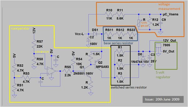
Except instead of three 1k ohm resistors in series there is one 3k ohm resistor as the base series.

I think it's odd I can find no other mention of this on the forum. I can't imagine all the extra heat a stock setup run at high voltages will produce is good for the controller.
 
If it helps, I have info on how I setup a switched resistor for mine, for 60V and below, or 72V and above:
http://www.endless-sphere.com/forums/viewtopic.php?p=284045#p284045

The resistors are in series, and are 330ohm and 33ohm, I think it is. I didn't note it in the post so I am going from the color bands in the original pic. (orange orange black gold, and brown black black orange orange). I would go measure them but I am not able to get up right now (legs are covered in sleeping St Bernard).

EDIT: nevermind, I found a followup post:
http://www.endless-sphere.com/forums/viewtopic.php?p=284411#p284411
where I found the above was a mistake and used a 470ohm instead of 33ohm.


However, your controller seems to be a different type for input resistors than mine (yours is probably a lot newer). So my resistances probably wont' help you. :(

I tried to find the posts in the Infineon / Xie Chang threads about figuring this out with math, but I can't find it right now. The posts I did find dont' describe or show anything like what is in that schematic, so they're not helpful. From what I can see, the "base series" resistors are fixed, and current always flows thru those. Then the "switched series" resistors are capable of being switched into parallel with the "base" ones, so current would only flow thru those when Q2 is on.

I presume that only happens when the voltage on the controller input is below a certain level, though I don't knwo what that level is. I'm sure it could easily be determined by calculating voltage drops across the resistors in those comparator circuits, and see where the trigger points are, but I don't think I can handle the math right now (or usually).

So the resistors that are used for high voltage are only teh "base" ones, the 3K in your case. The other ones shouldn't be hot (or even warm) as they shouldn't be in-circuit, AFAICS. If the "base" resistors are supposed to be ok up to 72V, and you are now going up to nearly 90V or more, then I think you can use the ratio of 90 to 72v to get a ratio of 1.25, and multiply that times your existing value of 3kohm, to get 3.75kohm. You can probably use a higher resistance and be ok, and stay cooler; might need experimentation.
 
If you have an EB2 or EB3, the resistor network looks a little different.

There is no reason that R12 and it's buddies should be getting hot though. All those do is adjust the voltage that the MCU sees downward into a level that it desires. The current flowing through it should be miniscule.

i had to modify mine recently, replaced a 1120 ohm tiny SMD resistor with an 830ohm to get regen at 100v. I've ran up to 125v on this controller.. mind you it is an 18FET with 4115's stock.

p.s. you're referring to R12 / R11, not R12B / R11B, right?

I do wonder what's up with your controller tho.. i wish you the best of luck.
 
AW, I big moose described it as a bang buck voltage regulator. It switches between both groups of resistors very quickly to maintain a steady voltage to feed the 5v voltage regulator. At least, that's how I understand it :|
 
Oh. Then I guess you'd need to apply that same ratio to both sets of big resistors?

Or you'd apply the ratio to the voltage dividers in the comparator section. Presumably only to one side of each divider, probably the high-side, but I am not certain.
 
What is the model number of your controller board? This schematic does not look like any boards I've bought from Lyen. Then again, I have only bought one linear regulated board from him. All the rest where SMPS, which run much cooler and waste less power. They also have a much broader input voltage range, 36 - 84V, based off one 200Ohm 2W resistor on R115 for the regulation circuit.

Also, R12 should definately not be running hot.
 
Ok - it turns out that these boards are supposed to get hot. The resistor values are fine. They just get hot.

http://endless-sphere.com/forums/viewtopic.php?f=2&t=10312&hilit=rs11&start=435

LFP had a possible soloution to help keep the resistors from overheating. Basically you wrap the legs of the resistors in copper wire and solder to enhance air flow and thermal capacity.

Qw59zl.jpg


Here's how it turned out. hopefully it'll help a little bit.
 
Hey auraslip, do you have any more pics of this board..in particular the area I have circled in red.

I have made a mess of the transistors and tracks in that area and can't find a schematic or anything to show me what is what
here is my thread about this
http://endless-sphere.com/forums/viewtopic.php?f=2&t=39825&p=582612#p582612

Cheers

Neil

 
Umm Thanks
Will have to look more closely at schematic, at first look I thought there was difference, so committed the ultimate sin of not reading further,but just scrolled down the post, saw the pic, and recognised the layout

Schematic has slightly different part numbers, and equivalent parts, so that is prob what threw me

Thanks

Neil
 
Yea that is probably a mod to run at higher voltages.

I found that in a 64 page thread on these controllers. There were standard 3 x 1k SMD resistors, and the mod seemed to be replace with 1 x 5 watt 3kOhm resistor

http://endless-sphere.com/forums/viewtopic.php?f=2&t=10312&hilit=methods+18fet+controller&start=240

100 volt mod also seemed to involve changing the three power resistors for 1.8 k instead of 1.5 K and modding R12 to keep the voltage sense point below 5 volt.

Is this controller of yours and old one? these controllers with this power input stage seem quite old..... Strange that you have started working on one at the same time as I have.

Be varey careful with running over 72 volts with it if it is the same as mine. Start increasing voltage slowly and monitor the voltage at the R11 R12 junction. I used a string of PC PSu's and a Meanwell with with an external pot on the voltage control point on the meanwell. O took the input voltage 1 volt at a time and measured voltage at various points. ANything above 8=o volt s in gave over 5 volts oout at R11 R12 voltage sense point. ANything over 5 volt here can blow the sense circuit in the MCU..I know i have zapped mine..now I have no LVC or regen

When I am bak in the worshop tomorrow, I'll post up my voltag emeasurements

if this sort of info was put in the wiki, then we would all not have to spen d time searching the forum. i made a start the other day with a bit about this..maybe you could go in and put any of your finding in there as well

here is what I started

http://endless-sphere.com/w/index.php/Brushless
 
Hope it can be of some help.
Seems to be many designs all with different variations, and I have been offered lots of info, but often related to different board types
So take care that the info I have given is accurate for your board. Looks pretty much the same from the Pics, but can never be 100 %
 
I am in workshop now..I'll take the paperwork with my voltage measurements home and post thme up later.

I am jsut clearing up down here


edit..cant find the papers..maybe they are at home after all
 
Guess I forgot to get back with my results eh? Well no idea now what I found.
But how did you get on with your board?
 
Why? What happened ? Did you kill it in some other way?

Or did an overvoltage issue blow the 5volt reg or MCU?
 
My umble advice is if the controler works fine and only problem is resistors to hot, keep the same values in resistance but double the power rating of them and as previously sugested leave a gap betwen the pcb and resistors so they dont warm up the rest of the components specialy the caps.

Updating the values of some components maybe will lead to a chain of failures in others. keep it simple.
 
auraslip said:
Lyen mentions that the resistor network may need to be changed if using a voltage other than 72v. I'm sitting at 22s, and I think this is causing my resistors to get burning hot to the touch. The paint on them is starting to melt, and I imagine all this heat is causing problems to the controller.

.

if it were just getting hot from normal use, I would agree, but the problem was stated in the first post that it is due to running higher than designed voltage. 22 so 92 volts ish..not 72.

So a resistor string change IS ( or was) required.

I did not do a change on one of mine Xlyte 18 FET) and eventually managed to destroy the voltage monitoring part of the MCU. I now have a working controller, but the MCU does not recognise voltage at the monitoring pin, so no LVC or regen.
 
Back
Top