Revolt 120 pro eTrial overheating problem

Hi Jonny
I too have had different experiences in design and transformation into electric vehicles.
I would like to give you some my opinion, so in general, and discuss some Reference datas to compare our projects.

The RV-120pro is a motor designed for the RC aeromodeling, therefore has special characteristics for this use, that are:
1) The propeller requires little torque at low revs, and this coincides with little cooling at low RPM of the motor.
2) The required torque rise by increasing the rpm, but has never sharp peaks.
3) Increasing the RPM, increases the torque and therefore the current in the stator, but also increases the speed of the model and then increases the cooling of the motor.

From this short list i can deduce that, to use RC aeromodeling motors in to "terrestrial" vehicles you must take care to:
1) Run the engine at high rpm, using short trasmission rate (and this applies to all air cooled engines).
2) Consequently use voltages the highest possible, and currents relatively lower.
3) Cool with an external source the motor (air and/or water) that cool it even at low RPM or even when stationary.

I have in the garage a bike that uses a chassis similar to yours, then i would imagine that it also has a base weight very similar.
On this bike (is that of my Avatar) i mounted a motor with nominal 7.5Kw (PERM Motor PMG132) at 3400rpm and with 20.5Nm nominal.
What is interesting is that to obtain the best performance, in Off-Road, i had to put a rate transmission of Z12/Z72.
The same rate we used on the motocross prototype "ROBO Stone 1.0" that uses a motor with 30KW and true 80nm peak.
I do not know if the rate that you are using is the definitive one, but it seems to me much longer than the engine can withstand a 6Kw (?) motor.

Here is instead a youtube channel that speaks of some electrical trial.
https://www.youtube.com/watch?v=S5U3XrdK6Ro

Regards
 
elo said:
Hi Jonny
I too have had different experiences in design and transformation into electric vehicles.
I would like to give you some my opinion, so in general, and discuss some Reference datas to compare our projects.

The RV-120pro is a motor designed for the RC aeromodeling, therefore has special characteristics for this use, that are:
1) The propeller requires little torque at low revs, and this coincides with little cooling at low RPM of the motor.
2) The required torque rise by increasing the rpm, but has never sharp peaks.
3) Increasing the RPM, increases the torque and therefore the current in the stator, but also increases the speed of the model and then increases the cooling of the motor.

From this short list i can deduce that, to use RC aeromodeling motors in to "terrestrial" vehicles you must take care to:
1) Run the engine at high rpm, using short trasmission rate (and this applies to all air cooled engines).
2) Consequently use voltages the highest possible, and currents relatively lower.
3) Cool with an external source the motor (air and/or water) that cool it even at low RPM or even when stationary.

yes elo, I totally agree with you.
Evaluate an electric engine relying only on power and torque data is insufficient, it is crucial understand for which kind of use it was designed.

To avoid complex reduction I choose to buy a low Kv engine, but now I think it would be better to choose a motor with higher kv and add a second stage reduction (sacrificing space for batteries)!

I think that the best approach is try to keep the original gearbox, unfortunately my bike have the clutch in oil bath (the same of the engine), so I was unable to successfully isolate the gearbox from the engine section. I also tough to use geese instead of oil, but I am afraid that it will not last.

I will try to adapt the revolt engine to my needs. Here my ideas:
- be sure that hall/phases are correct and the motor work at top of hits performance
- provide an airflow capable to manage at least 1 Kwatt of heat disspiation. I am looking at tangential fan (for server) or trying to put a fun directly attached to the engine shaft (not so easy to found).
- setting the PID parameter in the Controller to have the maximum acceleration ramp
- improve the reduction (13t/53t) by paying with a speed reduction, now the maximum speed is rated for 50Km/h, reducing it a 30Km/h for mountain trial will be acceptable


elo said:
I have in the garage a bike that uses a chassis similar to yours, then i would imagine that it also has a base weight very similar.
On this bike (is that of my Avatar) i mounted a motor with nominal 7.5Kw (PERM Motor PMG132) at 3400rpm and with 20.5Nm nominal.
What is interesting is that to obtain the best performance, in Off-Road, i had to put a rate transmission of Z12/Z72.

The same rate we used on the motocross prototype "ROBO Stone 1.0" that uses a motor with 30KW and true 80nm peak.

Wow, ROBO is a wonderful build!


elo said:
I do not know if the rate that you are using is the definitive one, but it seems to me much longer than the engine can withstand a 6Kw (?) motor.

The engine, at least from Revolt datasheet, is able to keep a 15kw of peak power (250amp @60v), I choose reduction to have 320 nm at wheel. I am going to review this values in a real world scenario

elo said:
Here is instead a youtube channel that speaks of some electrical trial.
https://www.youtube.com/watch?v=S5U3XrdK6Ro
Regards

Really nice video with a lot of infos!

Thanks elo for your suggestion!
 
Hi Jonny

- provide an airflow capable to manage at least 1 Kwatt of heat disspiation. I am looking at tangential fan (for server) or trying to put a fun directly attached to the engine shaft (not so easy to found).
:roll:
The 2 lateral flanges are made to work as fans, but I think are not be able to create air passing between the windings.
In fact it are designed as radial fans or tangential fans and it suck in air from close to the shaft and then centrifuged radially away from the shaft.
In practice I seem to understand that the 2 flanges are in competition with each other, and that is all and two push (or pull?) in the opposite direction, and the air in the center of the windings remain stationary, and so it warm up more it cannot.
I think it needs to make a new flange shaped as a fan.

The engine, at least from Revolt datasheet, is able to keep a 15kw of peak power (250amp @60v), I choose reduction to have 320 nm at wheel. I am going to review this values in a real world scenario
:idea:
Increase the battery voltage to 72V.
Run the engine at 2160rpm instead of 1800RPM increases the circulation of the air if you modify the flanges.
So you must short the transmission rate increasing the wheel torque.

Regards
 
Hi,
I am still stuck with overhearing problem of revolt engine.
I tried to check the alignment between phases and halls of my revolt using this Software Oscilloscope http://www.sillanumsoft.org/index.htm because I don't have a real one.

I connected the engine as described in the following pictures (as Fany suggested to me)
http://www.cerberotech.com/etrial/wiring_oscil.png

The software oscilloscope use my laptop sound card to take 2 channel samples. To avoid to destroy the sound card, I used a voltage divider made by to resistor to be sure to keep the voltage inside the range that can be sampled and managed from sound card.
This website made the calculation for me http://www.raltron.com/cust/tools/voltage_divider.asp.

Once the oscilloscope was connected to the motor, I spun the engine with an electric drill and get this value:

TEST 1 (monitoring yellow phase, green to the ground and get samples from the tree all sensors)

t1a.png

t1b.png

t1c.png


Some consideration:
  • sinusoidal signal is the phase signal, the fluctuations of the waveform are due to the drill that does not deliver constant power
    square signal, is not really square because the sound card capacitors affects the waveform, it do not really matter, the peaks are to be checked

TEST2 (monitoring yellow phase, blue to the ground and get samples from the tree all sensors

t2a.png

t2b.png

t2c.png


TEST3 (monitoring green phase, blue to the ground)

t3a.png

t3b.png


TEST4 (monitoring blue phase, green to the ground)

t4a.png


... the battery drill died...

Soon I am going to get a right interpretation of the tests result
 
Hello,
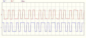
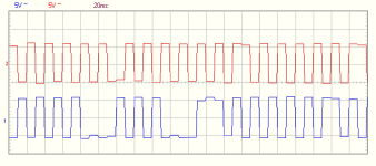
I tried my revolt motor with a scope. the hall signals are not good:
Image9.png
Image10.png
There is a lot of missing signals, inverted signals etc. I guess this is due to EMF noise from the phases as the halls are not shielded and miss pull-up resistor.
This is a reason for bad performance, if you can measure hall signals at the same time you drive the motor it will be clear if you have issues like this.
 
Hi lars,
yes not good at all!
What tool did you used to get the samples?

I will try to do the same to see if my motor has a similar behavior. Phase per Amp detected by the controller was extremely variable during engine constant spin, it can be caused by a incorrect hall signal.

What about to change the wiring of hall sensors? maybe using a shielded version? You should find a shielded cable that can pass through the small hole over the shaft.

I disassembled the engine to fix the temperature cable, I had cut during some assembly. Hall sensors seems to be correctly placed in the middle of two stators but the longitudinal position is not the same (I think that doesn't matter).

Hall1.PNG


Hall2.PNG


Hall3.PNG


here some other pictures of the disassembled engine for reference.

rv1.PNG


rv2.PNG
 
I think the deep position of the halls are a problem. They get shadowed by the tooth and distance to magnet is ~4mm.
I originally planned to put the new halls on the outside surface of the stator, meaning gap will be ~1mm
Cable shielding can be done outside of motor but is not easy inside as the wires are 1mm in dia and space is limited.

After seeing my signals i think about putting sensor magnets on the outside of motor and building a small sensor board.
 
My two bits:
- you can't have 6kW continous with 1800RPM, expect no more than 4kW continous at that speed
- this motor is quite hard to drive, lots of guys are struggling with controller settings
 
@boisrondevens:
Jonnydrives hall sensors are not symmetrical and would benefit from repositioning - i agree there.
As for the phase wire replacement: both my motors are OK so it is not always badly done at revolt but worth checking.
When replacing sensors, have you put them in the same deep location or did you move them? Do you use screened cables? I'd love to see a hall readout if you have it.

In my scope readouts it's obvious that 15-30% of the signals are not correct. If this is the case then a repositioned set of sensors will not improve performance much.

@jonnydrive: my readouts were done with a USB scope from Velleman. I think your readouts will be improved by probe calibration as the hall signals are not displayed as square (which they should).
 
@boisrondevens
I have seen a lot of positive feedback about the revolt from you, and even some close to impossible acceleration claims etc.
I would like to see some documentation to back up your claims. Some real test results with numbers, not just subjective opinions.
Even better would be a video to see what you are talking about. Got any of those?
 
upek said:
My two bits:
- you can't have 6kW continous with 1800RPM, expect no more than 4kW continous at that speed

What do you mean? There is some technical limitation or you say that basing on your experience?
Revolt assured me more than once that the engine is able to manage the power :(


upek said:
- this motor is quite hard to drive, lots of guys are struggling with controller settings

I hope that! I need a real torque engine, my tests do not provides torque as expected, probably because of some build problem.
 
larsb said:
I think the deep position of the halls are a problem. They get shadowed by the tooth and distance to magnet is ~4mm.
I originally planned to put the new halls on the outside surface of the stator, meaning gap will be ~1mm
Cable shielding can be done outside of motor but is not easy inside as the wires are 1mm in dia and space is limited.

After seeing my signals i think about putting sensor magnets on the outside of motor and building a small sensor board.

@larsb if you already have some idea to do that, I have a CNC router, we can try to build an hall sensors support that fits on our motor.
 
i'd use high temp epoxy for the sensor glueing. Like UHU endfest 300 or JB weld. Care must be taken with the JB weld as it is metal filled and leads current slightly.

And for the sensor board, i have my own CNC :D
I plan to mill in magnets into the end cover and place halls on the motor bracket. See the 14 purple holes in picture:
revolt motor with sensor magnets.jpg
I will use a bipolar latching type hall sensor Honeywell SS460P and mount them on the inside of the motor bracket.
 
larsb said:
i'd use high temp epoxy for the sensor glueing. Like UHU endfest 300 or JB weld. Care must be taken with the JB weld as it is metal filled and leads current slightly.

And for the sensor board, i have my own CNC :D
I plan to mill in magnets into the end cover and place halls on the motor bracket. See the 14 purple holes in picture:

I will use a bipolar latching type hall sensor Honeywell SS460P and mount them on the inside of the motor bracket.

This sounds like hardcore electrical engineer talk :). I assume it will give a clean hall signal?
Is this something you are doing to both your motors? I am watching with interest as I will have to make similar mods when I get around to my own rewind.
 
i am just pretending to be electrical engineer :D
There's so much info out there to read up on, eventually you learn something.

When i have a board design i'll post it as a step or STL so it can be CNC:ed or 3D printed. I wont make a silicon board but mill it from alu and do the wiring separately.
I will probably do it to both motors if it turns out well. It should be easy to get a clean signal compared to the environment inside the motor where you have coils with 200A current and the hall wires are right on top of them.
 
larsb said:
i am just pretending to be electrical engineer :D
There's so much info out there to read up on, eventually you learn something.

When i have a board design i'll post it as a step or STL so it can be CNC:ed or 3D printed. I wont make a silicon board but mill it from alu and do the wiring separately.
I will probably do it to both motors if it turns out well. It should be easy to get a clean signal compared to the environment inside the motor where you have coils with 200A current and the hall wires are right on top of them.

Have you considered to put the external Hall sensors on the back plate (the other side of the motor) of the engine instead of the front? On the back side of the motor there is a lot of space and no cables that can obstruct the halls cabling.
 
In my bike design i haven't got a good surface to mount on the rear side. It would be cleaner on rear side but i think it will be OK on the front side. The space occupied by cables are only half the circle.

It's in green in the pic, front end of mounting bracket
sensor mount.jpg
 
Wheazel said:
@boisrondevens
I have seen a lot of positive feedback about the revolt from you, and even some close to impossible acceleration claims etc.
I would like to see some documentation to back up your claims. Some real test results with numbers, not just subjective opinions.
Even better would be a video to see what you are talking about. Got any of those?


just for the record ( again) I'm not a sponsor or a associate to Revolt...

Voila

https://youtu.be/nWbPLBclem0
 
larsb said:
In my bike design i haven't got a good surface to mount on the rear side. It would be cleaner on rear side but i think it will be OK on the front side. The space occupied by cables are only half the circle.

It's in green in the pic, front end of mounting bracket

Nice bracket! what about water/dust protection?

I am facing a problem with a trade off between good air cooling (probably it will be made with forced air made by a tangential fan) and and dust/water protection.
 
On my motor the halls were the issue - check my idiots rewind thread.. from your issues i guess that same goes for you.

What are your plans now?
I'd get a hall readout, if they're not good then either claim warranty by revolt or change the hall position.
 
larsb said:
What are your plans now?
I'd get a hall readout, if they're not good then either claim warranty by revolt or change the hall position.

Hi larsb,
Revolt proposed me to buy a new motor with a discount price but I do not want waste other money with this kind of motors. Besides, I made the hall readings using your post as a guide and, unexpectedly, the readings was good, no missing signal in the square wave. Unfortunately the software I used save the data in a unknown/unreadable format (therefore I was unable to post the them on this forum).


To make my e-trial working I will try to put less stress on the motor by improving the gear reduction by machining a new 72t sprocket from a 8mm aluminium plate. I spent a lot of effort understanding how CAD/CAM tools works :shock:
I also decided to add an active air cooling system to the engine, the pieces are just arrived.

Likely it will not be the best solution, but I would like to have my first version of e-trial working by the summer!

Stefano
 
Back
Top