Rickys High Power Flexable motor controller

There's something called an angle-tracking demodulator that seems to be used pretty frequently with resolvers that have sin-cos outputs. It's basically a phase-locked loop that tracks the angle, which should be much more tolerant of non-sinusoidal waveforms. Even if you do have a pretty good sine shape, finding the angle directly with the arctangent is noisy and could also be computationally expensive on some of these chips.
 
fechter said:
Once the motor gets going above a certain speed, sensorless seems to work fine, but I don't think you will ever get it to work as well as sensored at startup and low speeds.


This is true for all conventional sensorless designs. There is a single type that can develop 100% starting torque at 0rpm. It's called flux-vector-control. It requires a controller to have 3 extremely fast dedicated precision inductance meters built into it, precisely taking an inductance reading between each phase almost instantly, comparing them against each other, and precisely plotting the rotor position from the relationships between these values, as the inductance fluctuates depending on the magnet's positional relationship to the teeth.
Sensors are way cheaper parts than using this method, and you're never going to see it in ebike controllers made by companies trying to make a product that can sell at a profit. It does work though.
 
liveforphysics said:
This is true for all conventional sensorless designs. There is a single type that can develop 100% starting torque at 0rpm. It's called flux-vector-control. It requires a controller to have 3 extremely fast dedicated precision inductance meters built into it, precisely taking an inductance reading between each phase almost instantly, comparing them against each other, and precisely plotting the rotor position from the relationships between these values, as the inductance fluctuates depending on the magnet's positional relationship to the teeth.
Sensors are way cheaper parts than using this method, and you're never going to see it in ebike controllers made by companies trying to make a product that can sell at a profit. It does work though.
Lukes right that vector control like I'm using should be able to do good startup but I'm still looking through different papers to find the best way but they use the changing inductance in one way or another. Some seem to be able to determine the rotor position but can't tell if they are 180deg out of phase so still looking but I'll get the high speed part running first.
The cost of the sensor is really a waste in that once the motor is going the sensor-less high speed should be more accurate than any affordable sensor.
One method injects a test frequency at a higher frequency than the motor drive frequency and analyses the rotor position based on that. Using this method the software knows the rotor position every 83us @ 12KHz.
Once the motor is fast enough the test signal is removed and the high speed sensorless algorithm takes over. So far I believe I have plenty of processing power to get it all working. Its just the usual lack of time that has been a problem. At least I have started getting back into the project a lot more since i finished my kitchen.
I'm definitely getting keen to get this on my bike so I should be a lot more focused on getting it running from now on and I've got past the boring PC interface part :lol:. Embedded software is much more fun for me than writing GUI apps.
The GUI config app will get some improvements but its functional enough that I can really start getting into the control code now.
 
rhitee05 said:
There's something called an angle-tracking demodulator that seems to be used pretty frequently with resolvers that have sin-cos outputs. It's basically a phase-locked loop that tracks the angle, which should be much more tolerant of non-sinusoidal waveforms. Even if you do have a pretty good sine shape, finding the angle directly with the arctangent is noisy and could also be computationally expensive on some of these chips.
Thats pretty much how I am going to try and use hall sensor inputs as an optional input to aid in startup until I get proper sensorless startup and as an alternative config option. Basically a PLL using an integrator to generate the angle for the controller and see how far it was off when the next hall signal changes. Not as dynamic as real angle sensors or sensor-less but might be sufficient for our purposes where vector control needs a continuous rotor position rather than 60deg spaced hall transitions.
I imagine this would work a lot better on a sin/cos input due to faster updates and less difference per update etc.
 
You don't need that high a speed to go sensorless... For me sensorless works down
to 60 e-rpm (or 1 Hz back-emf signals, 0.3V amplitude in my motor setup). My phase
information signal is measured at a rate of 80 kHz even at 60 e-rpm (using a 16 bit
DSP/MCU with 30 MIPS and 10 bit ADC's).

Forget about all the papers in the literature and do some independent thinking :D
sure it will give you a headache for 3 days :( but then you got a killer method
 
Lebowski said:
You don't need that high a speed to go sensorless... For me sensorless works down
to 60 e-rpm (or 1 Hz back-emf signals, 0.3V amplitude in my motor setup). My phase
information signal is measured at a rate of 80 kHz even at 60 e-rpm (using a 16 bit
DSP/MCU).
I figured it wouldn't be too high but was just referring to 'high speed' to differentiate if for the 'low speed' tricky region when really its any point where the back-emf can be seen above the noise but that gap between zero and usable back-emf is a critical gap in starting a bike unless you want to pedal off every time.
I Imagine this level will be quite dependant on the particular motor as well.
I haven't followed your thread too closely so I'm not sure what sort of control method you are running. I will have to find time to read through it.
 
Hope everyone had a merry christmas and has a great new year.

I couldn't leave my project alone but the problem with programming at this time of the year is...
ballmer_peak.png


I have actually made quite a bit of progress on the event logging subsystem today err yesterday...
but its really difficult to stay on the right place of the curve :lol:. I'm sure there is some truth to the curve above for me anyway :lol:.
Luckily I have SVN if I go too far and need to revert some suspect code.

Things I got going today
- Real time clock working properly and translated to unix time etc
- Automatic creation of log and event log dirs and daily event file creation.
- Event logging has its own task under FreeRTOS.
- Improved the protection scanning for trips and warnings so it can be easily configured to check different code modules.
- removed a chunk of old unnecessary debugging output thatwas cluttering up the serial port.

I just noticed today that adding code is no longer resulting in huge increases in binary size, I guess I have most of the bits of the newlib system library I need already added to the binary so now adding functionality doesn't increase the size much at all.

I have also charged up two of the SLAs that I have been loaned and one was in pretty poor shape (was down at 10.4V :shock:) but after a while its internal impedance seems to have dropped but it is still down on capacity but that shouldn't matter for the test I will use it for. It seems to have two cells that were way behind the other four in terms of charging (two cold while four warm. The other one i charged is fine.
The other two batteries seem to be in good nick and holding a good charge. Just need to give each a little thrashing on their own and a top off charge before connecting them in a string.
I'm just using my Turnigy Accucel 8150 to charge them in a controlled manor with statistics.
 
I broke one on my rules and now I have to fix it :evil:

I was getting ready to hook up the hall sensor inputs up to my hub motor. I had made a lead with appropriate plugs for the motor and controller on each end and checked that ok but had not connected it.

I then went and checked the pullup resistors were were doing their job with my meter and measured:
Hall_A 1.9V ???
HAll_B 4V
HAll_C 4V
hall_sensor_interface.png
I expected the 4V because the inputs are clamped at the micro board but the 1.9V suggests the micro was driving it and I thought the inputs were set to inputs so I need to check the software and for accidental shorts but while testing this I did something sillly and now the on board 5V regulator is flakey (Don't probe circuit boards late at night with poor light and lack of sleep) .
It works no load fine but with 110mA it won't regulate. The board runs fine with the 5V reg removed and a clean 5V fed in. the current draw is normal :?

When misbehaving the input voltage affected the output voltage that was too low. at 12.5V in from Vaux the board kept resetting. at 18Vin from a power supply the regulator put out about 4.5V so the board fired up. I hope it is the regulator and not some weird way for the board to latch up.
This is the first time I have seen it though apart from one other board where I managed to feed >20V into the regulator and killed the regulator.

Time to go hunting for my bag of 5V regulators cause it wasn't in the usual place :evil:. If I have run out its going to result in an ugly hack job.
 
Ricky_nz said:
(Don't probe circuit boards late at night with poor light and lack of sleep)

It's OK to do that if you have sufficient beer installed. Nothing can go wrong :twisted:
 
texaspyro said:
Ricky_nz said:
(Don't probe circuit boards late at night with poor light and lack of sleep)
It's OK to do that if you have sufficient beer installed. Nothing can go wrong :twisted:
Ahh thats my mistake. I only had one can of beer on board :lol:.
I couldn't find my bag of 5V regulators. I had some 7805 in the same package but the different pin out that wasn't going to work :(.
I then decided that proto board #1 was going to lose its regulator for a while and harvested the one from it, soldered it on the bad board and its up and running again :D.
Proto1 had some damaged tracks and I was going to use it as a CAN->USB adapter but thats not happening for a while so I've got time to order more regulators.

PS: I just put the repaired board back on the power stage and its sweet (motor running) so it was just a regulator :D. I guess all the clamp diodes protected the important parts but I would love to know why the regulator failed :?
 
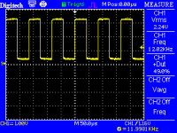
Look what I found on the HALL A input :shock:
look_what_i_found_on_hall_a.png
The measured 1.9V was with the controller tripped.
After looking at the schematic I noticed that the pins adjacent to the HALL_A input on the micro are MCPWM B0 (bottom FET of channel B) and HALL_B and since HALL_B was ok I thought I better check things closer.
I reset the trip and started the motor as it has run before and it fires up then I looked at the scope :shock:.
It would have really messed things up I had fed the hall in there while running :lol:
The culprit:
HALL_PWM_short.png
This was only the second 0.5mm flat pack I had soldered so thats my excuse.
It took probably less than a second to resolve :).
 
Ricky_nz said:
I guess all the clamp diodes protected the important parts but I would love to know why the regulator failed :?

Because you can't anti-Murphy *everything*. ;)
 
I just hooked up my golden motor 1000W hub to the controller outputs and run it on sinewaves generated from an integrator angle source so i had to spin it up slowly so as to not let it lose sync.
This was done on a 30V 2.5A PSU.

It actually nicely demonstrated the protection of my controller near the end where the voltage ripple on the DC bus gets too great so the controller trips and lets the motor cost down. That is the thud you hear near the end.

It is actually tolerant of my power supply going into current limit briefly causing the bus to drop a couple of volts for a while just like a sagging battery would do but it will trip on excessive ripple. Should help my caps live long healthy lives.

[youtube]RhkW9csLWiY[/youtube]

Now I need to get the hall inputs running.
I was thinking of spinning the motor up like above to do sensor calibration relative to the output current waveform.
It will also be interesting to see if angles recovered from hall sensors is good enough to close the angle loop of the FOC.
 
Ricky_nz said:
Ahh thats my mistake. I only had one can of beer on board :lol:.

You call yourself an engineer :roll: You have no business playing with high power electronics while sober :evil: Now go down to the boozeateria and get yourself sloshed all proper now. :twisted: We'll have no more of this namby pamby sober probing out of you.
 
Is this "beer on board" improvement due to:

1) alcohol lowering the conductivity of the body, avoiding dangerous shock current
2) alcohol raising the pain threshold so shocks don't hurt
3) alcohol making one not care that he just blew up the project, test equipment and computer, and perhaps burned down the shop
 
Alan B said:
3) alcohol making one not care that he just blew up the project, test equipment and computer, and perhaps burned down the shop
Im pretty sure if you put this into a C compiler and have it return print(f) you would get something like
alcohol==fun+(awesome/happy) :)
 
hillzofvalp said:
What are the highlights of this controller at this point?
I'll break it down into a couple of parts:-
Hardware:
- Universal control board that can be used with different power stages. with CAN and USB interfaces
- 12 FET (TO-247 package) power board as first power stage example (75V one built), I have FETS to assemble a 100V one

Goals:
- Feild Oriented control
- Sensorless operation from zero under load
- Things like Field weakening will just be a parameter as its just an input to the FOC, might need a few aother parameters to controll mapping it in etc.
- Support for sensors to be used if desired
- Able to drive "nasty" motors Low L etc.
- Well protected against failure and reliable. Should try hard to avoid frying FETS and Capacitors etc.
- Configurable as much as possible.
- current based throttle with programmable mappings etc
- CAN interface for monitoring / control etc.

What works:
- Lots of infrastructure that makes the rest easier :). This thing has lots of parameters and the number is growing daily so this became very important.
- Current control of FOC (no angle reference yet but its coming). SInewave generation as part of FOC.
- PC interface for setup / monitoring using USB
- Protections for most common fault conditions. over/under voltage, over current, ripply on bus voltage etc
- micro SD card logging of events.
- parameters stored on micro SD card.
- Phase current measurement
- All ADC inputs working and scaled as necessary.
- It easially runs my 80-100 Turnigy and also spins up my GM 1000W hub. haven't put much load on as until angle reference is added it loses sync although I have commanded up to 100A RMS / phase and it works.

-----

I got sidetracked with other things during the year but its great to get back onto this project :D.
I really need to keep a list like above and start moving things accross as completed.
I have probably missed a few things off. There is more planned features but I'll stick to this list first.
It definitly won't be the cheapest controller out there but reliability and smooth performance are goals
 
Your controller is one of the very coolest projects that's been attempted on this site Ricky. We are all pulling for you my friend.

I can't wait for the release of this beast.
 
hillzofvalp said:
I would pay $250-300 usd shipped for a warranted version.. Just to get you thinking about things
IM afraid its worth a lot more then that! I bet if he did 10 in a roe and flashed them all the same it would still take >8 hours start to finish!
 
I'm not sure it is inspiring to the inventor to tell him you are willing to pay below commodity prices for his unfinished work, and ask for a warranty.

Commercial controllers of this caliber sell for a lot more.

If he does make a product and does not charge enough it will cease to be available.

I hope this work is available in some form, either as a product, as intellectual property, or as open source information that can be used to study and create products by others.

Best of luck to you and your excellent project Ricky.
 
No, I agree with you. I'm sorry for sounding cheap... but I am cheap. give me your life's work for $200-300, please. :wink: After you sell your controller design to crystalyte for $80k.

I would think if you're building a controller this complex from scratch, you ought to have it with a pending patent...or some investors. How many different controllers have you built before?

I have faith in you.
 
Back
Top