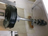
Shamrock, 25 foot sailboat electric conversion with an ebike hub motor

justin_le

Administrator
Staff member
Joined
May 28, 2007
Messages
2,310
Location
Vancouver
I've been meaning to post details about a sailboat conversion project in this watercraft forum for a while now but life she is busy! Anyways, I'll let the video do the initial introduction
[youtube]JuIG5Uqk4_c[/youtube]JuIG5Uqk4_c
 
Awesome project Justin, good luck on it

If I heard it right do you plan to also put some solar panels?
 
Balmorhea said:
That's a great market to break into if you like money.

Ha ha, no kidding there is that, but hopefully there's also market of boat owning DIY'ers who are into getting stuff outside the conventional big $$ marine channels.

Anyways I did a summary intro on this project a bit earlier this summer on another thread here:
https://endless-sphere.com/forums/viewtopic.php?f=39&t=98670#p1516816

But I'll do a recap. The boat is a Cal25 that I got several years ago as a 'hand me down' from some neighbors at our marina when they upgraded to a larger vessel. Originally everything ran fine, and it was a good first boat for me to learn how to sail and such. However last year I noticed that the oil consumption started increasing dramatically, like a liter ever 10hrs of run time, and often the oil pressure alarm would be buzzing for a few minutes after starting the engine.

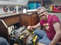
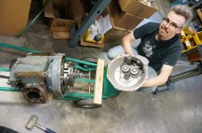
So it seemed a good time to haul out the engine to see what's up, and luckily my friend Arthur is super into everything about diesel (where I'm pretty out of my element)
Yanmar Removal.jpg

The idea of doing an electric hybrid drive was always my long term intention so this seemed like a great opportunity with the engine out to see if we could install an electric drive inline with the shaft to have a parallel hybrid system. I was thinking something 1000-1500 watts and enough battery that we could motor in and out of the harbor under all electric drive, and then run the diesel engine whenever we're doing longer coastal cruising trips and have the motor do regen to charge the batteries.

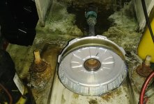
And a quick clearance fit test with a DD ebike motor shell showed that there was just enough clearance between the inside hull of the boat and the axis the coupling location to fit an outrunner motor right on the shaft like this:
Motor Shell on Shaft.jpg
 
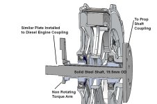
For this parallel hybrid drive we needed to have the propeller shaft going right through the hollow axle of the All Axle motor with a coupling on one side to transmit rotational power, while the other side of the motor axle would need to have a torque arm secured to the boat frame. Luckily I'd had experience doing almost exactly this same thing with the electric unicycle project.
https://endless-sphere.com/forums/viewtopic.php?t=18601

The propeller shaft on the boat is 1" diameter, while the hollow of the motor axle is 20mm, so I machined down a steel rode to like 19.5mm with a flange on one end to mate to the shaft coupling, and then in principle another coupling could be fit on the other end of the steel shaft that would mate to the diesel's output, something like this:

Motor Cutout with Axle Passthru.jpg


This way, the motor bearings aren't taking any load forces at all, the thrust of the propeller shaft just goes directly through to the face of the diesel engine and the motor just kindof floats on it.

The other issue with using ebike hub motors is KV related. The propeller is spinning around 1200-1400 rpm, but the fastest ebike motor winding we had on hand was 12.5 rpm/V. That would require like a 120V battery pack to reach the required speed. I really wanted to run the system off a 72V battery bank to be compatible with most of our ebike hardware and that meant sourcing a motor with a KV closer to 20 rpm/V, something you don't usually see in ebike hubs but sometimes do in the scooter/moped motor space.

Luckily on this front the 3 phase hub motors have a 'Y' connected windings, so it's possible to convert that into a Delta winding to boost the RPM/V by 73% and give a hub with the required 20 rpm/V.

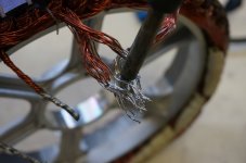
Here you see the common neutral point where all the common ends of the phase windings are soldered together. This is desoldered to individual strands, then a multimeter is used to match which strands were part of which colour phase on the other end.
Y Connection Desoldering.jpg

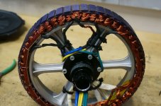
In this case rather than hooking up the 'delta' connections inside the hub, I decided to bring out all 6 phase leads to outside the axle, and that way it'd be possible to reconfigure as either delta or wye just by changing the termination at the motor controller. Plus in the delta mode the phase currents are also 73% higher for the same torque output so having the doubled up phase wires through the axle could better cope with that.
Delta Motor Connections.jpg
 
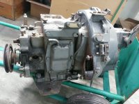
Anyways while that was all ticking along and looking promising for the parallel e-drive, me and Arthur were busy disassembling and and cleaning the diesel engine.
Yanmar on Cart.jpg
Transmission.jpg

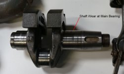
The parts with salt water cooling were a bit rough but most of the rest seemed in excellent shape considering the age of the engine. We ordered all the replacement piston rings and gaskets, reground the cylinder bore, checked the wear limits on the different parts and most were just within the allowable spec. However, when we got the crankshaft that was a different story, and the wear level at the main bearing was quite a bit worse than the service manual allowed. You can see it visibly in the picture here:
Crankshaft Wear.jpg

At that point we were looking at the cost of getting the crankshaft welded up and reground to spec, and I started to really wonder if this is the time to say screw it and commit 100% electric and put that money toward batteries instead. Not only would that simplify the motor design, the weight and space savings from leaving the engine out would make it way easier to install a large battery in its place.
 
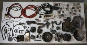
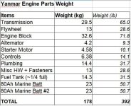
How much weight? Obviously the engine itself was heavy, but there is a surprising amount of weight that is also associated with all of the control parts, plumbing, exhaust system, starter motor, alternator motor etc. I decided one evening just to lay everything out weight all the pieces one by one and this is what I got

All Diesel Parts.jpg

Engine Weights.jpg

So 178kg, 392lb. The electric hub motor that is going to replace this by comparison is 4kg. That's less weight than just the starter motor of the diesel. It's less weight than the alternator. It's less weight than control rods going to the cockpit and back to adjust the throttle and flip to reverse. Just the hoses and exhaust plumbing for the diesel engine weight 3.5 times more than the electric motor. It really helps put that into perspective.

It also puts into perspective the simplicity of an electric motor. I mean there is beautiful mechanical magic in how a diesel keeps compressing, injecting, igniting, and expanding gasses with no electronic control once it's fired up, but it's heck of a lot of very precisely tuned pieces that all have to play nice together.

So the total weight removed from the boat with a 1/4 full tank of fuel was 178 kg. The electric motor is going to weight 4kg, figure another 4kg for the mounting bracket hardware and motor controller, and that left 170kg (375lb) available for batteries just to match the weight of the diesel system. 170kg of modern lithium cells would be 35 kilowatt-hours of battery capacity, and 35 kWhr of reserve seemed like it would be more than enough for any planned multi-day coastal cruising trips in the sailboat!

At this point the all-electric drive started to really make sense over the original parallel hybrid plan. Especially since if solar, wind, regen, and charging at Marina outlets weren't expected to cut it on a given trip, then we can just bring a portable 1000W gas generator to keep the bank topped up.
 
Very interesting conversion.

Just a thought:
Would the through axle design of the hub motor allow to stack 2 or more of these motors and slide a single axle through them while coupling the hub casings with an adapter between their brake rotor and cassette mounting holes? Thus creating a multi kW set up?
 
Like the idea that this conversion show the world the power of ebike technology. Oil based transportation is on the way out. Unbelievable weight saving. Will airplanes be next. Ebikes are fun.
 
SlowCo said:
Would the through axle design of the hub motor allow to stack 2 or more of these motors and slide a single axle through them while coupling the hub casings with an adapter between their brake rotor and cassette mounting holes? Thus creating a multi kW set up?

Totally. In principle with the thru-shaft design this would be one advantage and it's an appealing thought to make a modular/stackable motors like that. But from a system design it would always be more compact, efficient, and less expensive to just have a single wider stator motor when a higher power class is needed compared to two or more motors stacked back to back.

I've been looking into what it would take to have a 45mm wide stator version of this motor, not only for this sailboat drive application but also for higher power class fat tire ebikes that use 150mm front or 190mm rear dropout widths, where the current hub flanges are just too close together. My feeling so far is that this 27mm stator motor will be OK for sailbaots in the 22-28 foot size, but that boats over 30 feet would probably be best with a hub that's in more powerful class with a 40mm or wider stator instead.
 
For the battery bank I was a bit torn between running a whole bunch of 72V ebike batteries stacked in parallel, or getting some larger EV modules. The multiple-ebike packs keeps it in the theme of using ebike hardware for the build and gives tons of extra redundancy, but a few large EV modules might be more appropriate at this kind of capacity level.

Someone forwarded me a link to 4.5 kWhr 24V LiFePO4 modules from BYD on sale at batteryhookup.com for what they purported was $100/kwhr:
https://www.youtube.com/watch?v=i_V8v4APT60

That seemed like a sweet enough deal so I jumped on it. With 3 of those including shipping and purchasing 3rd party BMS boards it was about $1900 USD for a 14 KWhr 72V battery. In theory. We hoisted one of them up into the boat on the dry dock to sort how they would fit inside. It was definitely a 2 man job (modules are around 100lb each), and then the fit inside was a bit awkward.

LiFePO4 Battery.jpg

I was about to build all the hardware to install and secure these inside the boat but I wanted to run a discharge test on the packs just to check capacity after balancing all the cells and hooking up a BMS board. They were originally made as 200 amp-hour cells. The first pack I tested gave 150Ah, so not great but OK I guess given the price. But the next two modules only gave 134 and 125 Ah which was a real downer. At that rate whole series string would be just 9 KWhr (72V 125Ah) and use up most of our weight and room budget.

I didn't want to put so much effort setting up and mounting a battery that only had about 1/3rd the energy density of a new lithium-ion pack and which seemed already near end of life, but I also didn't want to have several dozen of downtube ebike batteries under the hold which are stylized to look good on a bike frame don't really stack together neatly in a square cavity.

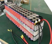
So I decided to go ahead and have a custom rectangular format battery built up by one of our vendors that would be better suited to both this boat project, and also to high power ebike builds. I went with 20s x 5p using 21700A panasonic cells in a long and skinny layout as you see here:
Naked 72V Pack.jpg

That gives a module of 72V 24.5Ah and weights a little under 7kg each. I had a sample run of 10 of these packs made up, they arrived just at the end of summer and fit into place perfectly!
Battery Bank.jpg

10 of these on the boat gives just over 17 KWhr of battery with only 70kg of weight added, with plenty of room to spare for more. In fact you can see I left one of the marine lead acid packs at the stern of the boat to help get enough ballast on the back to level the boat out more. I need more lithium ha!
 
Hi Justin, excellent project but a question if i may..
Have you checked /tested the effectiveness of the motor to power the boat ?
I am sure it will be work , but 1-2 kw seems marginal for a 25’ sailboat, especially if you anticipate open water excursions where sufficient power to overcome currents and wind is a safety concern
Its generally suggested that a 25’ sail boat would require 4hp (3+kW) for just 4 knots and another kW for 5 Kn.
https://betamarine.co.uk/engine-selection-for-yachts/
Perhaps you intend to run that motor up to 3-4 kW ?....is that possible and retain reliability.?
 
Thank you for sharing! I read this forum mostly for the RC airplane electric conversion and I have been trying to convert a 26' sailboat. I have since learnt quickly that the RC grade components are NOT suitable in the sailboat...

Now I am buying Electric cart components used from eb@ay to learn the trade.

1-Imperial Brushed PM ~20kg;
2-Alltrax AXE controller;
3- 10kWh A123 pouch cells ~100kg.

Really looking forward to learn from your conversion since the ebike components fit more on my budget.

Tai
 
Hillhater said:
Hi Justin, excellent project but a question if i may..
Have you checked /tested the effectiveness of the motor to power the boat ?

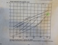
Ha, at this point yes indeed and I'll be sharing those results soon. But at the point when we filmed this first video it was still all theoretical that it should be OK. The reason I was pretty optimistic this would work out is because we had a close look at the published power curve of the Yanmar YSM-8 diesel engine.

Yanmar Power Curve.jpg

Assuming that our propeller curve matched this graph, then the max continuous power output we were getting with the diesel was 7hp (5200 watts) with the engine at 3200 rpm and the propeller at 1600 rpm (2:1 transmission).

1600 rpm times 2 Pi/60 is 167 rad/sec, so that means that the torque on the propeller shaft at full continuous power point is:

Torque = 5200 watts / 167 rad/sec = 31 Nm.

When I saw that things really clicked since 30 Nm is totally in the doable realm of ebike hub motors where we're often dealing with 50-80 Nm of torque off the line. Even the small little geared hub motors can do 30Nm for short times, but when you get in the continous realm it's usually somewhere between 25-35 Nm that most of the larger hub motors will top out before eventually overheating.

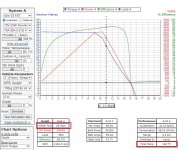
Here's what the prediction was like with the Grin motor set to a 21 KV with a 72V pack. If you drag the cursor left and right you see that the point where the final motor temperature transitions to just over 150oC, the motor torque output is basically right at 30 Nm. Bingo!

72V 21KV Motor Sim.jpg
https://www.ebikes.ca/tools/simulator.html?motor=MGRIN_FST&batt=B7223_AC&cont=cust_70_90_0.01_V&hp=0&wheel=2i&kv=21

And that's without any cooling modifications to the hub like Statorade or Vent holes. We are extrapolating quite a bit on the thermal predictions since I only did the wind tunnel testing at up to 400 rpm on the motor and never with zero wind speed, but it sure seemed like an encouraging starting place.

What seemed more likely to be bottle neck was the phaserunner motor controller. On a normal hub motor with a KV of like 8-10 rpm/V, you only need around 30 phase amps to do 30 Nm of torque. But on this faster motor wind of 21 rpm/V it's more like 60-70 phase amps to generate that much torque, and for the little 6 fet controller it would definitely go into thermal rollback after a couple minutes unless there was either forced airflow or water cooling on the controller heatsink.
 
So how did this all play out in practice? After putting the boat back in the water all sanded and painted, I started to crank up the power levels and noticed quite a bit of shaft vibration once we got up to about 1500 watts. The boat was moving at a good clip but you could feel it rattling loudly through the hull and I didn't want to push it any further than that.

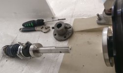
When I had it up on the dry dock I replaced the original worn down bronze shaft with a stainless steel unit and upgraded from a conventional packing nut system to a dripless shaft seal, both to keep a dry bilge and also to reduce the friction on the shaft seal which would add small errors to the torque measurement.
Shaft Seal.jpg

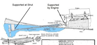
And I realized that the shaft seal through the stern tube doesn't give any actual shaft support, it's totally free floating inside there. The shaft is only really supported from the strut at one end and the motor mounting at the other end, and not anywhere along the length.

Shaft Supports.jpg

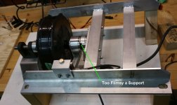
The diesel engine provided a super stiff and rigid mount for the shaft coupling on the front and would hold it perfectly on plane, but the way I had my electric motor hooked up to the load cells it could flex around quite a bit. I was only envisioning there being an axial thrust force and a torque force to deal with, but hadn't really considered shaft wobble pulling the motor sideways.

Load Cell Support.jpg

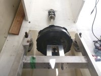
Anyways those are all solvable problems which just require a rethinking of the way that the force sensing instrumentation is done on the mounting block. But at this point the summer was slipping away and domestic discord was building up from the amount of time sucked into this project so decided to put off all the measurement stuff till later. Time to simply attach the motor with a solid aluminum plate with an added in a pillow block bearing too for good measure and then get sailing again!
Second Engine Installed.jpg
Pillow Block and Dripless Shaft Seal.jpg
 
Ah, ok..so with a few mods on the controller you should be able to achieve 3.5 kW continuous at the motor.
But, unless i am reading that chart wrong, that is at 1154 rpm ? ..450rpm down on the original set up resulting in a drop in boat speed with the existing prop.
Do you know what boat speed you were able to achieve with the diesel
Maybe you can find a better matched prop that would let you reduce the rpm down to the peak torque point (950rpm ?) and increase the boat speed up to the original.
There are several prop selector tools on line to aid that idea !
But, one step at a time. Test with the existing prop first to verify the theorys, then further changes if required.
Good luck
 
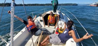
The first trip out with the updated motor mount was just pure bliss. The last time I'd taken the boat out was in January 2019 and we hauled out the diesel that spring, so it had been over a year and a half since the boat had power to leave the marina and it felt soooo good to be out on the water again.

Maiden Sea Trial.jpg

I had the controller maximum power set a little conservatively at 2000 watts since I wanted to slowly build confidence in the system before cranking it further. That was getting about 9.5 kph or just over 5 knots, which was enough to let us motor out under the lions gate bridge against the tide and get out for some sailing. For reference sake, full power with the diesel engine would let us cruise at 11 kph (6 knots), and that would require the equivalent of 5500-6000 watts of electrical input power.

That figure of 2000 watts at 9.5 kph also meant a consumption rate of 210 watt-hours / km, which meant that at this speed our 17kWhr battery pack would give us an 80km range under pure motor power with no sailing. And that was super encouraging. We have good friends who live on Gibsons which is 35-40km away so it seemed like the trip out should test the range limits and labour day weekend was coming right up.

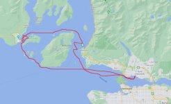
I didn't have a GPS logger properly setup at the time but the trip route was more or less like this:
Plumper Cove Trip.jpg

It was dead calm going out so we motored over the entire way there and tied off at the plumper cove marine park
Plumper Cove.jpg

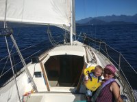
On the way back we had some really nice winds for the first half which let use sail around the north side of Bowen island
Sails Up.jpg
but then as happens out here the wind suddenly dropped to zero and so we were back to motoring for the 2nd half of the way home. And I should mention too on this trip that we were towing our rowboat as well, which reduced our 2000 watt speed from ~9.5 kph to more like 8.5-9 kph.
Towing Matelot.jpg

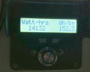
Once we got home in the evening the stats were 92km travelled over water using just over 14 kWhr.
WH per KM.jpg

There was juice to spare!
 
Hillhater said:
Did you have any data logging on the motor, current, temp, rpm , etc ?

You'd sure think so eh? I had a data logger plugged into the CA3 on the 92km loop but unfortunately the TRS cable had a break in it and it didn't log any data which was too bad, especially since this was also the first time I got to experiment a bit with regen too when the wind was blowing. I had gradually move the regen torque levels up and down to find the spot of maximum energy recapture.

So just last weekend we decided to make another trip out with all the logging gear properly configured. We did this trip out to lighthouse park and back with calm water and close to slack tide:

LighthouseParkTrip.jpg

Also I should mention at this point that in order to do meaningful data logging on ocean boat it was quite important to have a water speed sensor and not rely just on GPS speeds so that we wouldn't have to do tidal current corrections. I purchased a couple paddlewheel through-hull speed sensors on ebay hoping that at least one of them would be compatible with the CA's speed input signal. There was basically zero documentation I could find on interfacing with these things. One was clearly inductive based and wouldn't work, but the other unit from Lowrance had 3 wires and a shield and with trial and error I was able to figure out that the blue wire was 5V+, shield was Gnd, and when powered this way the orange wire would do a 0V pulse every time the sensor wheel rotated a quarter turn.
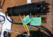
Speed Transducer.jpg

That was perfect, since it meant I could use the CA3's PAS pedal sensor input to measure the actual motor RPM from one of the motor hall signals, and get the speed signal for the CA3 from this water speed sensor by just empirically trying different wheel diameters until the CA's speed matched GPS speed at slack tides. I'm not sure that it's perfectly calibrated but it seems to be at least within 5% right now. And with that the CA can show boat speed, propeller RPM, motor temperature, and input power all on the main display screen.
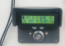
500W Speeds.jpg
3KW Speeds.jpg

And so here is the trip log:
Trip Analyzer Plot.jpg
https://www.ebikes.ca/tools/trip-analyzer.html?trip=F01sgC

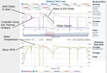
You can see that when we left we were able to run at 2800 watts for about 15 minutes while the motor temperature climbed up from 20oC to about 85oC. At that point the power decreased automatically leveling off at just under 2000 watts as a result of the motor controller going into thermal rollback, while the motor temperature continued to climb gradually to about 92oC. And that was more or less the steady state condition of our previous trip when I'd set a 2000 watt power limit in the controller.

At the 7km mark we stopped the motor for a second to inject 10mL of statorade into the hub and almost immediately it dropped down about 10 degrees
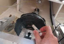
Statorade Injection.jpg

Then we rode continuously while changing the power in 250 watts steps and riding for a good several minutes at each power level to accumulate a nice average data. You can't just take a snapshot since the water speed sensor fluctuates up and down by about 0.5kph and upwards of 1-2 kph when you are bobbing up and down in the waves, so it's important to take a longer log and average the readings out.

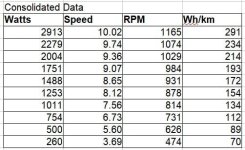
I finally did that just last night in order to answer your question and here are the results!
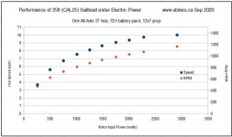
Boat Performance Plot in 250 Watt Steps.jpg

Consumption Stats.jpg

I expect once we put on a higher power motor controller and extend this data to 3500, 4000, 5000 watts we'll see the propeller shaft RPM continue to climb while the boat speed will gradually inch up to 11 kph, and consumption in the 500+ wh/km realm.

At the other end this also lets us see what our speed /distance coverage would be like under a pure solar scenario. I'm hoping to fit about 500 watts of solar on a rear arch (which needs to be built) and then an additional ~300 watts that could be put up on one side or the other (depending which didn't have shade) cantilevered off the stanchions. So in decent sunlight and no wind we should still be able to scoot around 5-6 kph without dipping into the battery reserve at all.
 
Amazing results justin.
At 1200 rpm you seem close to peak efficiency, but i wonder if a longer pitch prop would allow you to keep the 9-10 km/h speed whilst dropping the rpm below 900rpm and power down below <200W/km level ?
But , not so easy to trial different props on a sail drive ! :(
 
Hillhater said:
Amazing results justin.
At 1200 rpm you seem close to peak efficiency, but i wonder if a longer pitch prop would allow you to keep the 9-10 km/h speed whilst dropping the rpm below 900rpm and power down below <200W/km level ?

Yes, that is exactly what I want to know too! But I want to hold off those levels of tests until I have the torque sensor and thrust sensor systems hooked up. It will be an interesting question of tradeoffs because a lower RPM and longer pitch will mean more torque on the motor drive along with the lower RPM.

Right now if you look at the point where I was running the motor continuously at 2000 watts it shows that we are absolutely at the peak efficiency. So that the same power output at either a higher rpm with less torque or a lower rpm with more torque would mean a reduction in the actual motor efficiency.

https://www.ebikes.ca/tools/simulator.html?motor=MGRIN_FST&batt=B7223_AC&cont=cust_70_90_0.01_V&hp=0&wheel=1.97i&kv=21&throt=77&grade=13&mass=500
(simulated as a land vehicle to get the correct load and speed at that point - 50mm pitch, 500kg up 13% grade)
2000W Simulation Test.jpg

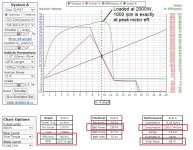
The big question is if the reduced motor efficiency will be more than compensated by a higher propeller efficiency or not. Right now we are running at about 88.5% motor efficiency with this propeller in this condition. Assuming we had a prop that was 50% higher pitch so that the 9.5 kph cruising speed was achieved at ~680 rpm instead of 1000 rpm, then the motor putting out 2000 watts at this lower RPM would be 86% efficient instead of 88.5%, and would reach hotter temperatures too.

2000W Simulation Test, higher pitch.jpg
https://www.ebikes.ca/tools/simulator.html?motor=MGRIN_FST&batt=B7223_AC&cont=cust_70_90_0.01_V&hp=0&wheel=2.95i&kv=21&throt=56&grade=12.8&mass=500

The big question then is if the the gain in propeller efficiency more than offsets the 2.5% drop in motor efficiency or not. My understanding is that these prop conditions (12" diameter 3 blade unit pushing a heavy boat at low displacement speeds) mean we're likely in the ~30-40% propeller efficiency range which is not very great. So if we could get like a 10% increase in propeller efficiency with a 2.5% drop in motor efficiency that would be worth it for sure, but with smaller gains maybe not.
 
Hillhater said:
Did you have any data logging on the motor, current, temp, rpm , etc ?

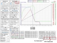
Also I forgot to comment on the temperature. You can see the temperature in the motor data plot and it had time to reach steady state during the 2000 watt cruising but not during the power level trials when we were only ~5 minutes at each power setting. On the departure before we added Statorade it leveled off right at 92 C (2000 watts power, 1000 rpm motor). On the way back after statorade was added to the hub the steady state temperature dropped to about 81 C.

I was a little surprised at how well this lined up with the simulator predictions, even though we never characterized the motor thermal behavior at near these kinds of RPM levels. The simulator thermal model is based on an assumption of forward air flow as a result of the vehicle moving forward for the given wheel diameter and RPM. In the boat's engine room there's no air moving forward, but there is turbulence caused by the fast spinning hub that produces local air flow around the side plates.

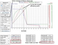
When I adjusted the equivalent wheel diameter to 40mm instead of 50mm then that seemed to create the same effect as locally induced air flow to match the measured steady state value of 92 degrees. And then with Statorade added the simulator predicted a motor temp of 81 degrees C, which is exactly what we saw in the sea trial.

https://www.ebikes.ca/tools/simulator.html?motor=MGRIN_FST&batt=B7223_AC&cont=cust_70_90_0.01_V&hp=0&wheel=1.57i&throt=76&grade=17&mass=500&kv=21&cont_b=cust_70_90_0.01_V&motor_b=MGRIN_FST_SA&batt_b=B7223_AC&wheel_b=1.57i&mass_b=500&hp_b=0&throt_b=76&grade_b=17&kv_b=21&bopen=true

Statorade Effect.jpg

This gives me a lot of confidence in the extrapolation of motor temperature predictions for what to expect with the motor at higher power levels. It SHOULD mean that we can totally do 5000 watts at 1500 rpm continuously with a larger motor controller. See:
https://www.ebikes.ca/tools/simulator.html?motor=MGRIN_FST_SA&batt=cust_90_0.01_80&cont=cust_70_90_0.01_V&hp=0&wheel=1.57i&throt=100&grade=18&mass=765&kv=21

The motor core will get close to 140oC, which is just approaching the limit of whats OK, and the efficiency is only slightly to the left of the peak point. At those speeds too just about any vane structure on the side plates would also do wonders to improve air cooling on the hub shell.
 
Hmm ? You have thrown me a bit now.
Why does the peak power change significantly on those charts ?
I am trying to understand the relationship between “ wheel dia” and boat speed ?..or the other outputs.
I guess this is a ratio you have derived empirically ?
 
Hillhater said:
Hmm ? You have thrown me a bit now.
Why does the peak power change significantly on those charts ?

Look at the % throttle setting. In the lower RPM chart with the higher pitch propeller I had to set the throttle to 56% in order that the 2000 watt input power point would happen at ~680 rpm, while with the stock propeller that is on the boat I wanted 2000 watts to happen at ~1000 rpm so used a 77% throttle.

I basically just played around moving the throttle level up and down to find at what point it the power at 680 rpm was 2000 watts, and I set the wheel diameter so that 680 rpm would show about 9.5kph on the speed axis because I figured that would be less confusing for people, even through there's no actual modeling of boat speeds or boat drags.

If you took that simulator link I provided and changed the X axis to be RPM instead of speed, then the wheel diameter detail wouldn't matter and you'd just see the performance of the motor at any given RPM and any given power level by playing with the throttle, like this:
https://www.ebikes.ca/tools/simulator.html?motor=MGRIN_FST&batt=B7223_AC&cont=cust_70_90_0.01_V&hp=0&wheel=2.95i&throt=79.6&grade=11&mass=500&kv=21&axis=rpm&autothrot=true

Here I set it to autothrottle, so if you click the cursor at the RPM you are interested in the cursor will stay there, and then use either the %Grade adjustment or use the vehicle weight to change the load on the motor at that RPM and then you can see the relationship between efficiency and power at that RPM point of interest.

Lemme know if that makes sense. It's a little bit of a roundabout way to get the info that we want while using a tool that was meant for land vehicles and adapting it for a boat.
 
Thanks Justin, i will work on that .
Meanwhile i came across this (whilst burrowing down a YouTube “rabbit hole”) .. which i found interesting.
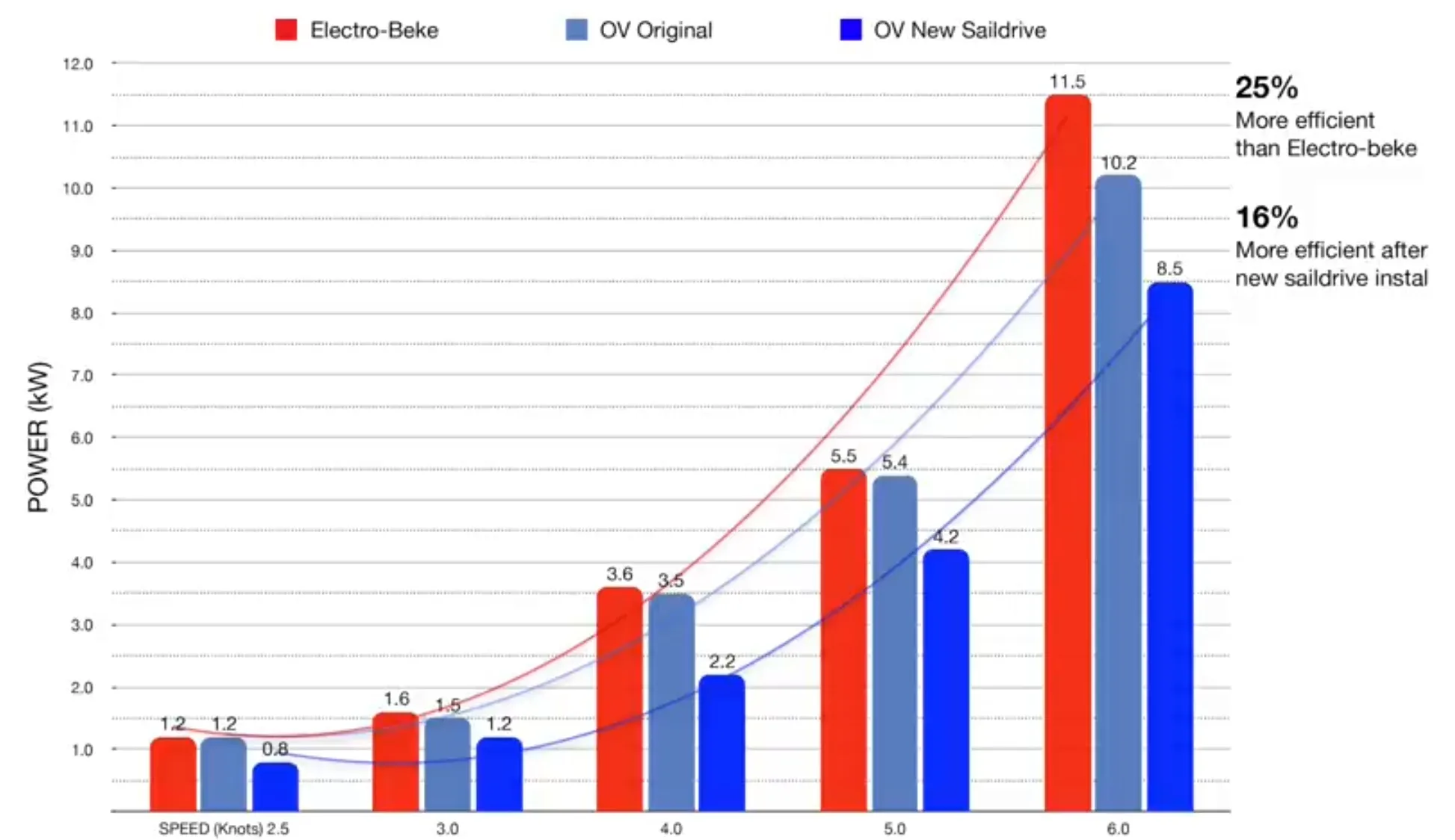
Its the test data from a “OceanVolt 8” electric saildrive fitted to a 36’ Pearson sail boat, ( The “Sailing UMA” series on UT, .. which you may have seen ?)
The “Electro-BEKE” data is from a 48v DC Fork lift motor in a through hull shaft drive, then changed it to the SailDrive from OceanVolt. (Ignor the “OV Original” data...that was from a defective drive)
I realise it is a much bigger, longer and heavier, boat ,..but the results up to 5kn (9kph) are double yours.
They also mention that Regen whilst under sail, gives them approx 250W at 6-7 kn...and 500+W if they catch a good blow and push past hull speed !
EDIT ..i should add..
Whilst it appears that there is a significant (25% ?). Reduction in power when using the Oceanvolt drive (compared to the Electro Beke ). That change also included a completely different propeller.
There were also some interesting comments over the different “characteristics” between the two Electrical drive systems !

VK5Qn6.jpg
 
Back
Top