scriewy
100 W
i got 2 controllers, clyte 24-72v 40a analog 12 4310 fets sensored and keywin 36-70v 20a 6 4110 fets sensorless.
clyte saw the wrath of Poseidon shorted in rain few months back, the smoke fairy visited inside it, since then i'v been using keywin.
few days ago i split 2 temporary 4s2p 14v 4ah packs that i was putting in series with other 56v 4ah to get 78v 4ah, i split to make 2 8s1p 28v 2ah each pack because thats how the rest are, but i automatically connected the 2 new 28v packs in series as before i connected the 2 14v in series and got sum of 110v+ and fried keywin controller. hm....
months back i opened clyte to see what presents the smoking fairy left, i saw 2 physically scorched fets on yellow phase, ordered 12 4110 for future upgrade and 4 4310 because i wanted to see if i'l be able to fix it.
the 4110 came long time ago, 4310 a month ago (different sellers).
so i basicly got 2 wounded that need engineerical attention. i'm checking both to see who's easyer to fix at this point.
removal of FETs from clyte:
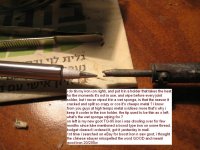
i sniped the legs of the cadaver fets, taking out was easy ha ha ! Relatively to soldering the new ones while they're legs are bent, took me 8 hours to change 2 fets with my special iron.

1 time solder flew between 2 legs of 1 new fet, i tried to clean it without removing it, HoLy fkn goat how hard it was to clear that from the new fet and the hols in the board before i put the new fets.
eventualy i'v done it, hooked controller turned on and poof - some 1 decided to lit a joint in my controller.
then i thought to find some answers before continuing to break stuff because i still had a working keywin, a week passed and i killed keywin.
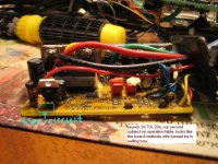
added to my arsenal of knowledge against the SMOKE GODS how to test capacitors (didn't find here) and FETs, the 3rd FET space you see on board is because i decided to take the new FETs out to test them if they're even alive after all the burning i did with my iron. took me 1 minute to remove it this time, so it's not a problem if any 1 will advise that.
i know inside 1 bank of FETs it's bad to mix different types of FETs because of different resistance and respons times, but can i put 1 bank of 1 type FETs and 2 other banks their own kind ?
like keep under 2 phases 4310 and on yellow to put 4 4110s ?
i got left with 1 spare 4310 while 2 utmost right FETs are still suspects.
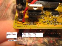
so till now i checked in clyte fets through phase wires and bat- bat+, set 200k on DMM, got the ok resistance on blue and green phases while yelow shows 0, then i checked resistance directly on FET legs, got same results on blue and green phases and a bit different at 1 FET on yellow. (i noticed FET values pic wasnt posted, i added it again but it's last now)
View attachment 3
can some fets stay opened after controller shuts off or they all should be closed ?
i dont wanna remove the utmost right 2 FETs unless it's the only way to check if they're alive, they dont show any visual sign of damage, the brown stuff is resin i burned while soldering 8 hours 2 FETs , i checked the big caps with analog meter they're ok, i checked some resistors i noticed repeat near each phase on the back side of board and they test same values.
tell me what stuff next inline could'v got hit that i should check before i put new FETs in so they dont fry because something ells is cruked, tell me where to stick the probes , i'l upload more pics from point zero before i removed the dead FETs.
second wounded - keywin

on the keywin controller i checked FETs and at some point they all went zero infinite ohm, later i noticed DMM wire in lead wore out n torn, fixed it but had to go to work, still gota check caps on it, and how to test the LM317 ? since it's the first thing that gets hit by overvoltage as i learnd here.
clues - when i turn controller power ON turnigy wattmeter reads 0.07ah, then at 110v i turned it on and saw same numbers, i twisted slightly the throttle, motor did little jilt and wattmeter reading jumped to 0.280ah.
what parts should i check after such incident ?

forgot to upload a pic of my super IRON ~~!
adited the post a bit, now through clear mind i noticed it was not so clear yesterday when i was very very tired.
when i check FETs onboard what is of interest to us, capacitance between gate to drain, gate to source or drain to source ?
Any way to know in caps where is - and + if legs of same length ? When i switched analog meter leads it jumps below 0 and starts to charge again R rises to infinity.
clyte saw the wrath of Poseidon shorted in rain few months back, the smoke fairy visited inside it, since then i'v been using keywin.
few days ago i split 2 temporary 4s2p 14v 4ah packs that i was putting in series with other 56v 4ah to get 78v 4ah, i split to make 2 8s1p 28v 2ah each pack because thats how the rest are, but i automatically connected the 2 new 28v packs in series as before i connected the 2 14v in series and got sum of 110v+ and fried keywin controller. hm....
months back i opened clyte to see what presents the smoking fairy left, i saw 2 physically scorched fets on yellow phase, ordered 12 4110 for future upgrade and 4 4310 because i wanted to see if i'l be able to fix it.
the 4110 came long time ago, 4310 a month ago (different sellers).
so i basicly got 2 wounded that need engineerical attention. i'm checking both to see who's easyer to fix at this point.
removal of FETs from clyte:
i sniped the legs of the cadaver fets, taking out was easy ha ha ! Relatively to soldering the new ones while they're legs are bent, took me 8 hours to change 2 fets with my special iron.

1 time solder flew between 2 legs of 1 new fet, i tried to clean it without removing it, HoLy fkn goat how hard
eventualy i'v done it, hooked controller turned on and poof - some 1 decided to lit a joint in my controller.
then i thought to find some answers before continuing to break stuff because i still had a working keywin, a week passed and i killed keywin.
added to my arsenal of knowledge against the SMOKE GODS how to test capacitors (didn't find here) and FETs, the 3rd FET space you see on board is because i decided to take the new FETs out to test them if they're even alive after all the burning i did with my iron. took me 1 minute to remove it this time, so it's not a problem if any 1 will advise that.
i know inside 1 bank of FETs it's bad to mix different types of FETs because of different resistance and respons times, but can i put 1 bank of 1 type FETs and 2 other banks their own kind ?
like keep under 2 phases 4310 and on yellow to put 4 4110s ?
i got left with 1 spare 4310 while 2 utmost right FETs are still suspects.
so till now i checked in clyte fets through phase wires and bat- bat+, set 200k on DMM, got the ok resistance on blue and green phases while yelow shows 0, then i checked resistance directly on FET legs, got same results on blue and green phases and a bit different at 1 FET on yellow. (i noticed FET values pic wasnt posted, i added it again but it's last now)
View attachment 3
can some fets stay opened after controller shuts off or they all should be closed ?
i dont wanna remove the utmost right 2 FETs unless it's the only way to check if they're alive, they dont show any visual sign of damage, the brown stuff is resin i burned while soldering 8 hours 2 FETs
tell me what stuff next inline could'v got hit that i should check before i put new FETs in so they dont fry because something ells is cruked, tell me where to stick the probes
second wounded - keywin

on the keywin controller i checked FETs and at some point they all went zero infinite ohm, later i noticed DMM wire in lead wore out n torn, fixed it but had to go to work, still gota check caps on it, and how to test the LM317 ? since it's the first thing that gets hit by overvoltage as i learnd here.
clues - when i turn controller power ON turnigy wattmeter reads 0.07ah, then at 110v i turned it on and saw same numbers, i twisted slightly the throttle, motor did little jilt and wattmeter reading jumped to 0.280ah.
what parts should i check after such incident ?

forgot to upload a pic of my super IRON ~~!
adited the post a bit, now through clear mind i noticed it was not so clear yesterday when i was very very tired.
when i check FETs onboard what is of interest to us, capacitance between gate to drain, gate to source or drain to source ?
Any way to know in caps where is - and + if legs of same length ? When i switched analog meter leads it jumps below 0 and starts to charge again R rises to infinity.


